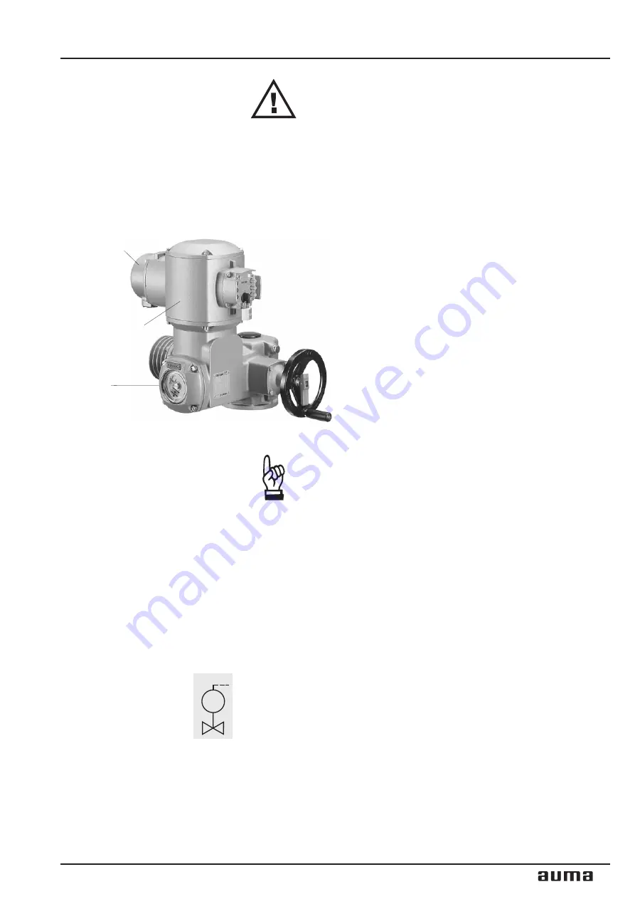
AUMA plug/socket connector
(customer connection XK)
Switch
compartment cover
AUMA VARIOMATIC
6.
Electrical connection
Work on the electrical system or equipment must only be
carried out by a skilled electrician himself or by specially
instructed personnel under the control and supervision of
such an electrician and in accordance with the applicable
electrical engineering rules.
AUMA actuators SARV are operated by the electronic controls
AUMA VARIOMATIC. The controls may either be mounted di-
rectly to the actuator or to a separate wall bracket.
The electrical connection to the power supply is made at a
plug / socket connector with screw cable terminations as
standard.
When installing the AUMA VARIOMATIC on a wall bracket, ob-
serve the following points:
1) For position feedback an electronic position transmitter
(RWG) in 3-wire system must be used.
2) For the connection of actuator and AUMARVARIOMATIC on
wall bracket, use additionally suitable flexible and screened
connecting cables.
3) The max. permissible cable length between multi-turn
actuator and AUMA VARIOMATIC is 25 m.
.
Check if type of current, supply voltage and frequency
correspond to motor data (refer to motor name plate).
.
Remove plug cover (AUMA plug / socket connector)
(figure G).
.
Loosen screws and remove socket carrier from plug
cover.
.
Insert cable glands suitable for connecting cables.
.
Enclosure protection IP 67 is only ensured if suitable
cable glands are used.
.
Connect cables according to order related wiring diagram CI S. . . KMS
14TP . . .. The wiring diagram belonging to the actuator is attached to the
handwheel in a weather-proof bag, together with the operation
instructions. In case the wiring diagram is not available, it can be obtained
from AUMA (state commission no., refer to name plate).
Cross sectional areas:
controls cables max. 2,5 mm
2
,
power supply max. 6 mm
2
.
.
Connect heater via external voltage source so that condensation is
prevented.
.
Only the same potential can be switched through the two circuits of the
switch. Different potentials require tandem switches.
Versions with gold-plated microswitches (option) may only be loaded with
small voltages (50 V DC / 400 mA).
.
The valve manufacturer specifies whether switching off in the end
positions should be via limit switch (limit seating) or torque switch
(torque seating).
.
For the connection of position transmitters (potentiometers) screened
cables must be used.
.
Insert socket carrier and fasten.
.
Clean sealing faces at plug cover, terminal compartment cover and check
if O-ring is o.k.. Apply a thin film of non-acidic grease (e.g. Vaseline) to
the sealing faces.
.
Place cover and fasten 4 bolts evenly crosswise.
.
Fasten cable glands securely to ensure enclosure protection IP 67.
9
Multi-turn actuators SARV 07.1 - SARV 10.1
Operation instructions
AUMA VARIOMATIC
MOV
M
Figure G


