background image

S/M No. : TCM003NEF0

Содержание DTH-14U1

Страница 1: ...S M No TCM003NEF0 ...

Страница 2: ...structions 20 Service mode adjustments 20 Assembly adjustments 21 SCHEMATIC DIAGRAM 25 PRINTED CIRCUIT BOARD 26 Exploded View 27 Service Parts List Recommendable Spare Parts List 32 APPENDIX Appendix is provided only by internet http svc dwe co kr IC Description 38 Troubleshooting Guide 46 No power 46 No picture 47 No sound 48 CH don t stop 49 No color 50 No vertical deflection 50 No on screen dis...

Страница 3: ...N THE ONLY POTENTIAL SOURCE OF X RAYS IN CURRENT T V RECEIVERS IS THE PICTURE TUBE HOWEVER THIS TUBE DOES NOT EMIT X RAYS WHEN THE HIGH VOLT AGE IS AT THE FACTORY SPECIFIED LEVEL THE PROPER VALUE IS GIVEN IN THE APPLICABLE SCHEMATIC OPERATION AT HIGHER VOLT AGES MAY CAUSE A FAILURE OF THE PICTURE TUBE OR HIGH VOLTAGE SUPPLY AND UNDER CERTAIN CIRCUMSTANCES AMY PRODUCE RADIA TION IN EXCESS OF DESIRA...

Страница 4: ...l shock hazard and must be corrected imme diately PRODUCT SAFETY SERVICING GUIDELINES FOR COLOR TELEVISION RECEIVERS GRAPHIC SYMBOLS The ligntning flash with arrowhead symbol within an equilateral triangle is intended to alert the service personnel to the presence of uninsu lated dangerous voltage that may be of suff cienty magnitude to constitute a risk of electric shock The exclamation point wit...

Страница 5: ...n 4 Wall and shelf mounted installations using a commercial mounting kit must follow the factory approved mounting instructions A receiver mounted to a shelf or platform must retain its original feet or the equivalent thickness in spacers to provide adequate are flow across the bottom bolts or screws used for fasteners must not touch and parts or wiring Perform leakage test on cus tomized installa...

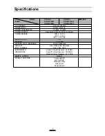
Страница 6: ... 2 13 12 UHF 2 13 56 CATV 1 125 125 SOUND OUTPUT 3W SPEAKER 3 W 16 ohm ANTENNA INPUT IMPEDANCE 75 ohm Unbalanced AUXILIARY Front Video Audio Ear phone INPUT TERMINAL Rear Video Audio INTERMEDIATE Picture IF Carrier Frequency 45 75 MHz FREQUENCIES Sound IF Carrier Frequency 45 25 MHz Color Sub Carrier Frequency 42 17 MHz REMOTE CONTROL R 43A01 SPCEIAL FUNCTIONS 3 Language OSD With CAPTION Wake up O...

Страница 7: ...Y red indicatior This indicator lights up when the AC power cord is connected to a power source 6 Remote Control Receiver This receiver receives a signal from your remote control Do not block it 7 VIDEO IN jack Use this jack to receive a video signal from another A V component 8 AUDIO IN jack Use this jack to receive an audio signal from another A V componet 9 EARPHONE jack Use this jack to receiv...

Страница 8: ...system or to change audio and video settings 5 MENU Use this button to turn the TV s menu system on and off 6 DISPLAY Use this button to select the TV s signal source 7 INPUT Use this button to select the TV s signal source 8 VIDEO Use this button to display video adjustment items 9 0 9 Use these buttons to change channels 10 SLEEP Use this button to program the TV turn off after a certain time 11...

Страница 9: ...e the CH buttons to select Reception the use the VOL button to select Air or Cable If you connected an antenna to your TV select Air If you connected a cable system select Cable 3 Use the CH buttons to select Memorize Channels then use the VOL button to enter the Memorize Channels process Again press the VOL button to begin 4 Press the MENU button to return to Set Up menu 5 Press the MENU button t...

Страница 10: ...he TV s Channel Memory Your TV s memory determines the channels that are available using the CH buttons You can add channels to this memory or remove them from memory If a channel is removed from memory you can tune to with the number buttons but you cannot tune to it with the CH buttons If there are just one channel memorized then the Add Delete Channels function will search the whole channels Bu...

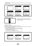
Страница 11: ... the TV s Input Normally your TV displays the signal coming through the antenna terminal However If you ve connected another component to yourTV such as a VCR using theVideo Audio input you will want to be able to view the signal from the component To do this you will need to switch from the TV input to the Line Input as follows 1 With the TV on press the MENU button twice then set up menu will ap...

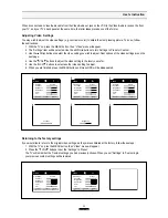
Страница 12: ...t another video setting to adjust 6 When you are finished press the MENU button until menu OSD will be disappeared Select Video Settings Custom Contrast Brightness Sharpness Color Tint Adjust Next 1 Select Video Settings Preset Contrast Brightness Sharpness Color Tint Adjust Next 2 Select Video Settings Preset Contrast Brightness Sharpness Color Tint Adjust Next 3 Contrast 4 Brightness 5 6 Returni...

Страница 13: ...nes seem too red or purple press the VOL button if flesh tones are too green press the VOL button Using Timer Functions Your TV has a built in clock and you can set the TV to turn on and off at times that you select You can also set your TV to turn off after counting down a certain amount of time Setting the Clock 1 With the TV turned on press the MENU button until Time menu will be displayed 2 Th...

Страница 14: ...ock 12 00 AM Wake Up time Off time Sleep Timer 0 min Adjust Next 3 Setting Off Timer If you enter a time in the Off time setting your TV will automatically turn off at that time Follow these instrutions to set the Off time 1 With the TV turned on press the MENU button until Time menu will be displayed 2 Use the CH buttons to select Off time item 3 If you hold down either VOL or VOL button the corr...

Страница 15: ...lable sleep times see step 3 one by one To cancel the Sleep timer turn the TV off or set the sleep time to 0 using one of the methods described above Select Time Set Clock 1 2 00 AM Wake Up time 06 30 AM Off time 1 1 30 PM Sleep Timer 0 min Adjust Next 1 Select Time Set Clock 1 2 00 AM Wake Up time 06 30 AM Off time 1 1 30 PM Sleep Timer 0 min Adjust Next 2 Select Time Set Clock 1 2 00 AM Wake Up ...

Страница 16: ...conds or press the MENU button to return to normal TV viewing Your setting will remain intact until you change it Closed Caption OFF CC on Mute OFF Power Restore OFF System AUTO Select Special Adjust Exit 1 Closed Caption C1 CC on Mute OFF Power Restore OFF System AUTO Select Special Adjust Exit 2 1 Closed Caption T1 CC on Mute OFF Power Restore OFF System AUTO Select Special Adjust Exit 2 2 CC on...

Страница 17: ...ecial Adjust Exit 3 System User can select the AUTO PAL M PAL N NTSC color system modes If you have no color problem when see the FF mode of VCR or non standard signal you must choose the NTSC of color system modes 1 With the TV turned on press the MENU button until Special menu will be displayued 2 Use the CH buttons select system item 3 Use the VOL buttons to selcet AUTO PAL M PAL N or NTSC Clos...

Страница 18: ...t may be a station problem Check that the antenna is connected and is in good working order has no broken wiresm and is adjusted correctly The picture is OK but the sound is poor Try another station If the other stations are OK it may be station problem Check that the antenna is connected is in good working order has no broken wires and adjusted correctly There is poor reception on some channels T...

Страница 19: ...ct wiring not our own improper installation unauthorized modification or to use in violation of instructions furnished by us nor units which have been repaired or altered outside of our factory nor to cases where the serial number thereof has been removed defaced or changed This warranty is in lieu of all warranties expressed or implied and no representative or person is authorized to assume for u...

Страница 20: ...19 Block Diagram ...

Страница 21: ...color of selected item turns into the red Press the volume up or down button to enter in the service mode you wish to adjust 2 How to memorize the adjusted values in the service mode Must press DISPLAY button the state which the screen is displaying each of service menus after all adjustments are completed each of all service menu Table A Adjust the values of service mode when a part is replaced P...

Страница 22: ... White Display internal 100 WHITE Internal 60 White Display internal 60 WHITE Internal Cross Pattern Display internal CROSS pattern Red Drive RD 0 127 Align RED OUT AC level Green Drive GD 14 0 15 Must be set to 14 Blue Drive BD 0 127 Align BLUE OUT AC level Red Bias RB 0 255 Align RED OUT DC level Green Bias GB 0 255 Align GREEN OUT DC level Blue Bias BB 0 255 Align BLUE OUT DC level Subbrightnes...

Страница 23: ...ta 4 GEOMETRIC ADJUSTMENTS S6 Enter the service mode and select service adjustment S7 Whenever you select the S7 using the volume up or down button the screen is changing like this NORMAL BLACK WHITE100 WHITE60 CROSS Using the volume up or down button select internal cross pattern Select service adjustment S6 You can see the OSD as shown in below 4 1 Horizontal Position Adjustment Select H PHASE i...

Страница 24: ...tment S8 You can see the OSD as shown in below Using volume up or volume down adjust service adjustment data of RD GD BD and RB GB BB until a good gray scale with normal whites is obtained ALIGNMENT INSTRUCTIONS Press the DISPLAY button to memorize the data 6 DIGITAL PRESET D P ADJUSTMENTS S9 SUBBRIGHTNESS ADJUSTMENT Receive a good local channel Enter the service mode and select service adjustment...

Страница 25: ...rightness level Press the DISPLAY button to memorize the data CONTRAST Fixed value 27 TINT Fixed value 35 COLOR Fixed value 25 7 FACTORY OUTGOING MODE S12 FACT If you select the S12 then the set becomes factory outgoing status You can see the OSD outgoing OK Alignment Instructions ...

Страница 26: ...25 SCHEMATIC DIAGRAM ...

Страница 27: ...26 EXPLODED VIEW 1 DTH 141 ...

Страница 28: ...27 EXPLODED VIEW 2 DTH 201 ...

Страница 29: ...28 EXPLODED VIEW 3 DTH 14U1 ...

Страница 30: ...29 EXPLODED VIEW 4 DTH 20U1 ...

Страница 31: ...30 EXPLODED VIEW 5 DTH 14V4FSN ...

Страница 32: ...31 EXPLODED VIEW 6 DTH 20V4FSN ...

Страница 33: ...AUTION Parts recommended for stock Safety critical component Replace only with genuine Daewoo safety part PTMPMSH529 PCB MAIN MANUAL AS DTH 14V1FSN C101 CEXF1H109V C ELECTRO 50V RSS 1MF 5X11 TP C102 CEXF1C101V C ELECTRO 16V RSS 100MF 6 3X11 TP C103 CEXF1H229V C ELECTRO 50V RSS 2 2MF 5X11 TP C104 CMXM2A333J C MYLAR 100V 0 033MF J TP C105 CEXF1C471V C ELECTRO 16V RSS 470MF 10X12 5 TP C106 CEXF1H109V...

Страница 34: ...TP C513 CEXF1H109V C ELECTRO 50V RSS 1MF 5X11 TP C514 CEXF1C471V C ELECTRO 16V RSS 470MF 10X12 5 TP C515 CEXD1H229F C ELECTRO 50V RND 2 2MF 5X11 TP C516 CEXF1H478V C ELECTRO 50V RSS 0 47MF 5X11 TP C518 CEXF1H478V C ELECTRO 50V RSS 0 47MF 5X11 TP C520 CEXF1H109V C ELECTRO 50V RSS 1MF 5X11 TP C521 CEXF1H100V C ELECTRO 50V RSS 10MF 5X11 TP C523 CEXF1H470V C ELECTRO 50V RSS 47MF 6 3X11 TP C524 CEXF1H1...

Страница 35: ...08T 25T C 20T ULW 300 LOC PART CODE PART NAME DESCRIPTION LOC PART CODE PART NAME DESCRIPTION Service Parts List PWC1 4859909110 CORD POWER AS LP 16 H03VVH2 F TUBE 2600 Q401 TKSC2330Y TR KSC2330Y TP Q402 T2SD2627 TR T2SD2627 R Q403 TKSC945CY TR KSC 945C Y TAPPING Q601 TKSC945CY TR KSC 945C Y TAPPING Q602 TKSC945CY TR KSC 945C Y TAPPING Q603 TKSC945CY TR KSC 945C Y TAPPING Q701 TKSC945CY TR KSC 945...

Страница 36: ... FILM 1 6 4 7K OHM J R709 RD AZ152J R CARBON FILM 1 6 1 5K OHM J R710 RD AZ103J R CARBON FILM 1 6 10K OHM J R711 RD AZ102J R CARBON FILM 1 6 1K OHM J R712 RD AZ473J R CARBON FILM 1 6 47K OHM J R713 RD AZ102J R CARBON FILM 1 6 1K OHM J R714 RD AZ102J R CARBON FILM 1 6 1K OHM J R715 RD AZ102J R CARBON FILM 1 6 1K OHM J R716 RD AZ103J R CARBON FILM 1 6 10K OHM J R717 RD AZ471J R CARBON FILM 1 6 470 O...

Страница 37: ...201J R CARBON FILM 1 6 200 OHM J R909 RD AZ201J R CARBON FILM 1 6 200 OHM J R911 RD AZ101J R CARBON FILM 1 6 100 OHM J R912 RD AZ101J R CARBON FILM 1 6 100 OHM J R913 RD AZ101J R CARBON FILM 1 6 100 OHM J R914 RD 2Z332J R CARBON FILM 1 2 3 3K OHM J R915 RD 2Z332J R CARBON FILM 1 2 3 3K OHM J R916 RD 2Z332J R CARBON FILM 1 2 3 3K OHM J R921 RD AZ102J R CARBON FILM 1 6 1K OHM J R922 RD AZ472J R CARB...

Страница 38: ...01B479JS 1W 4 7 OHM J SMALL R452 R CARBON FILM RD 4Z123J 1 4 12K OHM J RD 4Z113J 1 4 11K OHM J R503 R CARBON FILM RD 4Z822J 1 6 8 2K OHM J RD AZ752J 1 6 7 5K OHM J Q402 TR T2SD2627YB T2SD2627 TFJA6806D TFJA6806D R883 POSISTOR DJ140M290L J503P53D140M290L DDC7R0M290 ECPCD7R0M290 V01 COIL DY 58D0000082 ODY M1489 48A96420N1 ODY M2050 V901 CRT 48A96314C5 A34AGT13X R 4859630461 A48JLL91X50 M16 ZZ131 COI...

Страница 39: ...38 IC Description U COM I701 APPENDIX ...

Страница 40: ...of 16 x 32 dot characters used 16K bytes Various characters attributes Character colors 16 colors Character background colors 16 colors Fringe shadow colors 16 colors Full screen colors 16 colors Rounding Underline Italic character slanting Attribute can be changed without spacing Vertical display start line number can be set for each row independently Row can be overlapped Horizontal display star...

Страница 41: ...PLL IC Interface FS 181 Channel AIR 2 69CH CABLE 1 125CH AFT Operation FineTuning 2 5Fn 2 5MHz AIR CABLE STD HRC IRC Only Cable 5 6 CH is that AFT range is cover over broad band 2 5MHzFn 3 5MHz Memorize Channels If a channel is broadcasting the channel is memorized DirectTuning 09KEY Channel Up Down Memorized Channels The Ch Up Down buttons on the Remocon and on the front panel are same function S...

Страница 42: ... SPA POR E2PROM Interface I2C Bus Control CH 6 TRAP Function IS 31 PLL IC Band Data Control Byte 2 P3 P0 VHF L 1 VHF H 2 CH6TRAP 5 IS 31 AIR Cable CH 6 Only UHF 8 5 The Table of Option and Schedule Model Name Pin Option Application Reference CM 003N Low DC_0V Video High DC_5V TV Low DC_0V Air High DC_5V Cable Low DC_0V Stereo High DC_5V Mono Low DC_0V Blue Back High DC_5V No Use No Use No Use 4 8 ...

Страница 43: ...to Tint Low DC_0V No Auto Tint High DC_54 PHILCO LOW DC_0V NON GND Negative power supply It uses 32 768KHz X TAL 10 pin is input terminal for crystal oscillator 11 pin is output terminal for crystal oscillator 5V 0 5V Positive power supply Power Ch up down Vol up down Menu DC value that comes from the 10 pin of LA76810 14 Connect this port to AGC of Tuner Default Voltage 3 75V Variable Voltages 3 ...

Страница 44: ...age Green output terminal of RGB image Blue output terminal of RGB image Fast blanking control signal Switch TV image signal and caption OSD image signal Output terminal Intensity output terminal of RGB image signal Output terminal 6 bit input output port Input output can be specified for each bit Other function IC Description 16 17 18 19 21 23 25 26 27 P87 AN7 RES FILT CVIN HS G BL I P60 SDA 0 I ...

Страница 45: ...1 P06 Video White Use when TV set turns off Use when does power off on Power Off Output Low DC 0V Power On Output High DC 5V 33 34 35 P72 INT 2 TO IN P72 INT 3 T0 IN P00 31 P70 INT 0 Sound Input 32 P71 INT 1 N C SD In R F R F H L V INT0 E E D E E 03H INT1 E E D E E 0BH INT2 E E E D D 13H INT3 E E E D D 1BH P70 INT0input HOLDrelease input Nch Tr output for watchdog timer P71 INT1 input HOLD release...

Страница 46: ...45 IC Description I101 LA76805 IC VIDEO PROCESSOR APPENDIX ...

Страница 47: ...46 Troubleshooting Guide 1 NO POWER APPENDIX ...

Страница 48: ...47 Troubleshooting Guide 2 NO PICTURE NG Go to the figure OK Go the figure Check the waveform of I101 46 APPENDIX ...

Страница 49: ...48 Troubleshooting Guide 3 NO SOUND NG Go to the figure OK Go the figure Check audio output signal of I101 1 APPENDIX ...

Страница 50: ...49 Troubleshooting Guide 4 CH DON T STOP NG Loss of signal or weak signal OK Go to the figure Check the input signal conditions APPENDIX ...

Страница 51: ...50 Troubleshooting Guide 5 NO COLOR 6 NO VERTICAL DEFLECTION APPENDIX ...

Страница 52: ...51 Troubleshooting Guide 7 NO ON SCREEN DISPLAY 8 REMOTE CONTROL DOES NOT OPERATE APPENDIX ...

Страница 53: ...SAAVEDRA LAMAS 1480 9420 RIO GRANDE PROVINCIA TIERRA DEL FUEGO ARGENTINA AUDIVIC S A ...

Отзывы: