35
10.2 Jumper settings
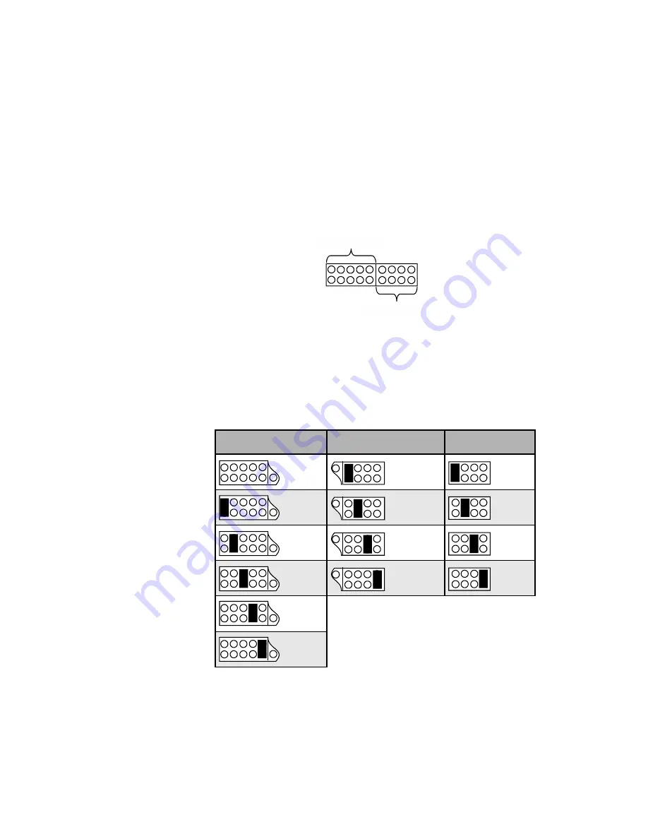
The jumper fields in center of the module determine the gain. Please refer
to the table below to find the jumper setting for the desired gain. Addition-
ally, the gain is printed on the board right beside the jumper position.
The jumper field for selecting the input impedance is divided into two sep-
arate areas. The first five jumper positions (counted from the left) are for
selecting the input resistance; the remaining four positions determine the
input capacitance.
Again, the values are printed on the board right beside the jumper positions.
To setup 68 k
W
input resistance please remove the corresponding jumper.
The following table lists all possible position and the corresponding values:
Input resistance
Input capacitance
Gain
68 k
W
110 pF
38 dB
47 k
W
160 pF
48 dB
33 k
W
220 pF
58 dB
2,2 k
W
330 pF
68 dB
470
W
100
W
10.3 MM pickup systems
For MM pickup systems set the gain to 38 dB, i.e. put the jumper in the
left position (labelled '38' on the board, also see table above). For the
Input resistance
Input capacitance
Содержание SAM 20 SE
Страница 1: ...1 audionet SAM 20 SE Stereo Amplifier User s Manual...
Страница 2: ...2...


