6
4.0 f u n c t i o n a l t e s t s
These notes are provided to assist you in servicing the amplifier. The circuit schematics are marked
with typical voltage levels, which may assist in defining the cause of any problem.
4.1
Test equipment required
Equipment
Digital Multimeter
Dual Tracking DC Power
Supply
Various Leads
Specification
Accuracy better than 0.5% in V and mV ranges
Output: ±32 V DC 2 A
Positive terminal of negative supply must be connected to
negative terminal of the positive supply unless internally linked
V
mA
V
mA
-ve
+ve
-ve
+ve
Select Tracking
0 V
+32 V
-32 V
Black = -ve
Red
= +ve
Green = 0 V
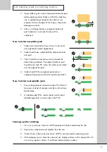
Figure 4.1 - Functional test set-up
Содержание 8000S
Страница 1: ...service manual Integrated amplifier 8000S ...
Страница 24: ...24 7 0 c i rc u i t s c h e m a t i c s 7 8 Digital system controller schematic SCH26701 02 01 ...
Страница 25: ...25 7 0 c i rc u i t s c h e m a t i c s 7 9 Digital system interface schematic SCH26701 03 01 ...
Страница 26: ...26 1 7 0 c i rc u i t s c h e m a t i c s 7 10 1 Input interface schematic SCH26701 04 04 BZV86 2V0 ...
Страница 27: ...27 7 0 c i rc u i t s c h e m a t i c s 7 11 Relay coils schematic SCH26701 05 01 ...
Страница 28: ...28 7 0 c i rc u i t s c h e m a t i c s 7 12 Front panel schematic SCH26702 01 01 ...
Страница 29: ...29 7 0 c i rc u i t s c h e m a t i c s 7 13 Speaker outputs schematic SCH26703 01 01 ...


