


15
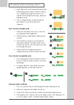
5.0 p e r f o r m a n c e t e s t s
.2 ms/div
400 mV/div
1
.2 ms/div
2.00 V/div
2
2
1
Figure 5.2 Protection circuit waveforms
5.2
Performance test procedure
For test point
(TP)
references, see section 6.0 Test Points.
No
5.2.19.
5.2.20.
5.2.21.
5.2.22.
5.2.23.
Action
Right channel
check mute
operation
reverse polarity
Reassemble unit
Noise check
Check
operation of
remote
controller
Clean with
damp cloth
Test Equipment
Multimeter set to
diode test
Connect to CD
player and
preamplifier and
play a TAG
McLaren Audio Test
Tracks CD
Details
Connect positive probe to 0 V
(TP 0)
.
Connect negative probe to input socket
signal pin
(TP 22)
.
Make sure amplifier mutes.
Disconnect positive probe.
Make sure mute relay resets (not muted).
Relay will click.
Remove all leads
Reconnect loudspeaker connections and
listen to audio output for good audio
performance.
Check remote funtions:
volume
input selection
muting
Содержание 8000S
Страница 1: ...service manual Integrated amplifier 8000S ...
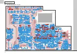
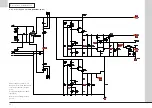
Страница 24: ...24 7 0 c i rc u i t s c h e m a t i c s 7 8 Digital system controller schematic SCH26701 02 01 ...
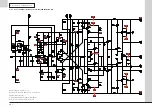
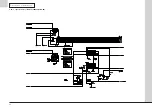
Страница 25: ...25 7 0 c i rc u i t s c h e m a t i c s 7 9 Digital system interface schematic SCH26701 03 01 ...
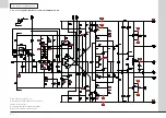
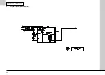
Страница 26: ...26 1 7 0 c i rc u i t s c h e m a t i c s 7 10 1 Input interface schematic SCH26701 04 04 BZV86 2V0 ...
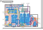
Страница 27: ...27 7 0 c i rc u i t s c h e m a t i c s 7 11 Relay coils schematic SCH26701 05 01 ...
Страница 28: ...28 7 0 c i rc u i t s c h e m a t i c s 7 12 Front panel schematic SCH26702 01 01 ...
Страница 29: ...29 7 0 c i rc u i t s c h e m a t i c s 7 13 Speaker outputs schematic SCH26703 01 01 ...