12
5.0 p e r f o r m a n c e t e s t s
No
5.2.1.
5.2.2.
5.2.3.
5.2.4.
5.2.5.
5.2.6.
5.2.7.
5.2.8.
5.2.9.
Action
Switch off AC
power button
Connect
amplifier as
shown in
Figure 5.1
Switch on AC
power button
Adjust volume
knob to
maximum
Measure output
of preamplifier
Measure output
of power
amplifier
Reduce
VOLUME
knob to
minimum
Set
OUTPUT
to 20 V rms
Measure
distortion at
1 kHz
Test Equipment
Audio Analyser
output connected to
both left and right
CD inputs
8
Ω
load
Audio Analyser
output: 1kHz,
100 mV rms
Multimeter set to
mV AC
Audio Analyser
output: 1kHz,
100 mV rms
200Hz HP filter on
A-weighted filter off
Audio Analyser
output: 1kHz,
1 V rms
200Hz HP filter on
A-weighted filter off
Audio Analyser
output 1kHz,
1 V rms
200Hz HP filter on
A-weighted filter off
Details
Output frequency:
1 kHz sine wave
Output voltage:
100 mV rms
Reading settings:
AC level, Auto,
200 Hz HP filter on
A-weighted filter off
Select
cd
using
INPUT
selector knob.
Select
pre
using
MODE
selector knob.
Measure output of left and right
PRE
AMP
sockets.
Voltage should be 286 mV rms
±10 mV rms.
Select
integrated
using
MODE
selector
knob.
Measure output of left and right
loudspeaker terminals.
Voltage should be 8 V rms ±0.2 V rms.
Increase volume until amplifier
OUTPUT
is 20 V rms. If signal is increased further,
amplifier will begin to clip.
Distortion of left and right channels should
be <0.006%
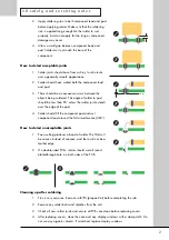
5.2
Performance test procedure
For test point
(TP)
references, see section 6.0 Test Points.
Содержание 8000S
Страница 1: ...service manual Integrated amplifier 8000S ...
Страница 24: ...24 7 0 c i rc u i t s c h e m a t i c s 7 8 Digital system controller schematic SCH26701 02 01 ...
Страница 25: ...25 7 0 c i rc u i t s c h e m a t i c s 7 9 Digital system interface schematic SCH26701 03 01 ...
Страница 26: ...26 1 7 0 c i rc u i t s c h e m a t i c s 7 10 1 Input interface schematic SCH26701 04 04 BZV86 2V0 ...
Страница 27: ...27 7 0 c i rc u i t s c h e m a t i c s 7 11 Relay coils schematic SCH26701 05 01 ...
Страница 28: ...28 7 0 c i rc u i t s c h e m a t i c s 7 12 Front panel schematic SCH26702 01 01 ...
Страница 29: ...29 7 0 c i rc u i t s c h e m a t i c s 7 13 Speaker outputs schematic SCH26703 01 01 ...


