Version 5.4
11
May 2008
SIP Hardware Installation Manual
2. Physical Description
2 Physical
Description
This section provides a physical description of the device.
2.1 Components
The device includes the following components:
A 19-inch, 2U high rack-mount chassis (refer to ''Chassis'' on page
Hot-swappable communication blades and rear transition modules (RTM), as listed in
the table below:
Table
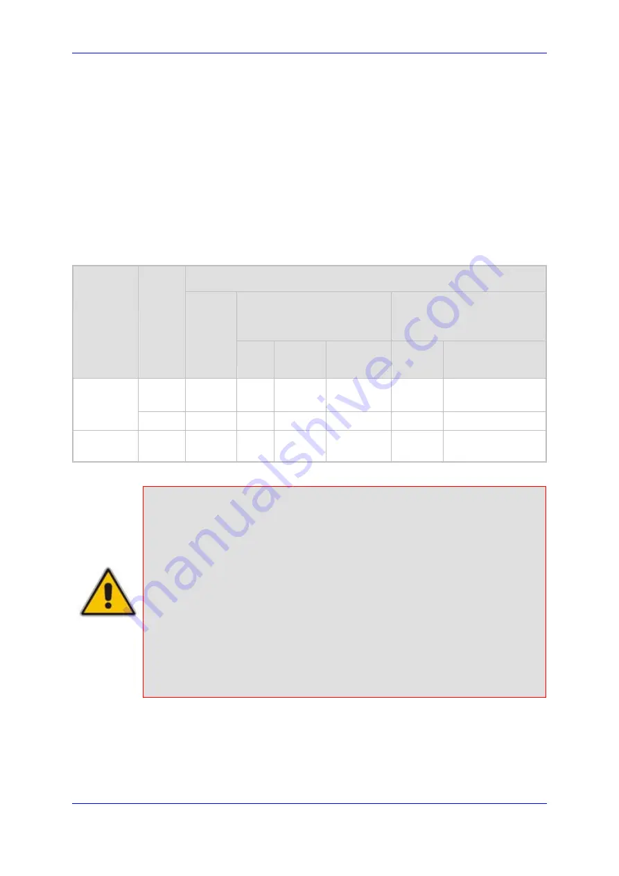
2-1: Number of Communication Blades/RTMs per Device
Number of cPCI Blades
6310 Series
8410 Series
System
Mode
SA/M3K
6310 RTM-6310 RTM-6310
Redundant
8410
RTM-8410
Simplex
1 1 1
--
1
2 for 42-84 spans
1 for 16 spans
Mediant
3000
HA 2 2 1
1
2
2
IPmedia
3000
Simplex
1 1 1
--
1
1
Notes:
•
The device either implements the 6310 (refer to ''6310 Blade'' on page
) or 8410 (refer to ''8410 Blade'' on page
) blade series.
•
RTM
refers to Rear Transition Module.
•
HA
refers to 1+1 High Availability mode, supported only by Mediant 3000
(i.e., not IPmedia 3000).
•
HA for 16-spans 8410 blade configuration will be supported in the next
applicable release.
•
The blades are housed in the chassis' front-panel slots; the RTMs are
housed in the chassis' rear-panel slots. For the blades' slot assignment in
the chassis, refer to ''Card Cage and Slot Assignment'' on page
•
The Alarm and Status blades (SA/M3K) are housed in the chassis' front-
panel slots (refer to ''SA/M3K Alarm and Status Blade'' on page
Содержание TP-6310
Страница 1: ...Document LTRT 94701 May 2008 Hardware Installation Manual Version 5 4...
Страница 2: ......
Страница 10: ...SIP Hardware Installation Manual 10 Document LTRT 94701 3000 Series Gateways Media Servers Reader s Notes...
Страница 42: ...SIP Hardware Installation Manual 42 Document LTRT 94701 3000 Series Gateways Media Servers Reader s Notes...
Страница 70: ...Hardware Installation Manual Version 5 4 www audiocodes com...


