


Web Remote
66
Saving presets
1
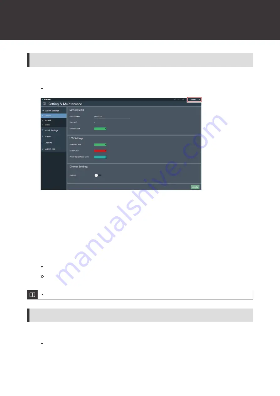
Click “Preset”.
“Preset” shows the name of the current preset.
2
Click “Save Preset” in the pull-down menu.
3
Click the slot where the preset is to be saved.
4
Enter a name.
5
Click “Save”.
It may take several minutes to save presets.
Settings for the microphone are saved in the preset.
For information on importing and exporting presets, see "Presets" (p. 61) in Setting & Maintenance.
Recalling presets
1
Click “Preset”.
“Preset” shows the name of the current preset.
Содержание ATND1061DAN
Страница 1: ...ATND1061DAN Beamforming Array Microphone User Manual Main Unit Edition English...
Страница 18: ...Installation 17 1 2 1 Zip tie 2 Tab on surface mount adapter 10 Tighten the zip tie to secure...
Страница 31: ...Installation 30 Flush mounting Completed installation...
Страница 42: ...Installation 41...
Страница 77: ...76 Dimensions ATND1061DAN 227 5 30 227 5 Unit mm...
Страница 79: ...Dimensions 78 Flush mount adapter 307 34 5 39 307 283 105 283 70 38 1 Unit mm 2 2 2 4 M 4...


