29
DEMO PRODUCT INSTALLATION
It is now time to begin installing the audio-video components. If you’ve followed the instructions so far, you will have a
working system in short order. It may be a good idea to map out a wiring plan for the audio and video components before
you begin connecting them to the switching system and to AC power. Make sure you will have access to the switching
modules from either the front or rear of your fixture shelving.
Usually, it works out best to mount the components to be located at the bottom of your display first, and work towards
the top of the display so you can avoid masses of hookup wire hanging down from above. Remember that the position of
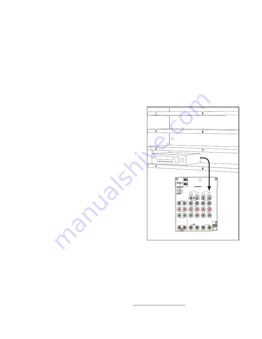
each component on the shelf should match the number you wish the control panel to display. For instance, in
Figure 50
the component in the display is on the bottom shelf, so it should be connected to the set of jacks on the switching module
for component number 4. The Control Panel will now display “04” when this component is selected.
Be sure to save the boxes and accessories for the components so that you can offer your customer a new or almost new
unit when you later take the component out of the display.
1. Install the First Products.
Install one product in each group in order to get a simple system
running. For example, install a source, a receiver, a pair of front
speakers and a TV monitor. Leave your power source on but be
careful using metal tools. If your system does not include PSBs,
ignore any references to PSBs.
A. Sources
Connect a source to an AC power outlet and its low-level audio
or A-V outputs to a product position on the source module (
See
Appendix B for hookup diagram.
)
• Connect the source unit to the product position on a
922 or a 955 Switch Module.
• Connect the low-level output to the source module’s
red (R) and white (L) female RCA jacks, and
connect composite video output to the yellow RCA
jacks if demonstrated.
• Connect Digital Audio outputs to a 955 module. If
coaxial outputs are not available, use a converter
such as a Model 977T.
• Connect the plug of the PSB’s cable (if PSBs
are used and are not already hooked up) to
the PSB port next to the arrow with the number
corresponding to the source you are connecting.
See Figure 40.
• Install the device in your shelving or cabinet.
B. Receivers
Connect a receiver to AC power. Then connect the receiver’s
audio inputs and speaker outputs to the 945 or 942 Receiver
Selector (
See Appendix B for hookup diagram.
)
• Connect the receiver to the Audio jacks using high quality RCA and/or optical cables.
• Use 14 or 16 gauge speaker wire to connect the unit’s speaker outputs to the corresponding terminal plug
(front, center, surround). If you are switching subwoofers with low-level, use RCA patch cords to connect the
Subwoofer output from the receiver to the 945.
• If you plan to use video on-screen programming, connect HDMI ports on the receiver to the appropriate
switches and distribution amps as shown here: audioauthority.com/hdmi-audio.
• Install the unit in your shelving or cabinet.
SYSTEM
BUS
GROUP
EXP
ANSION
Audio/Video Source Selector
ASD
Model 955
PSB
10-19
0-
9
PSB
RIGHT AUDIO
LEFT AUDI
O
SOURCES
4
3
2
1
MODULE ID
DIGITAL AUDIO INPUT
COMPOSITE VIDEO
A/V SOURCE BUS
POWER
701-1088
3
2
BYP
ASS
Figure 50.
Содержание Access EZ 922
Страница 1: ...Demonstration Network Home Audio and Video System Installation Manual...
Страница 2: ......
Страница 22: ...22 Model 906G Control Panel Model 903 Control Panel Product Select Buttons Custom Third Party Touchscreen...
Страница 32: ...32...
Страница 51: ......


