23
INSTALLING A CONTROL METHOD
1. Installing a Control Panel
Skip this step if you do not have a 903 or 906G Control Panel. If you have a 903 Control Panel, it is accompanied by a
separate User’s Guide which you should locate for future reference.
Note: The 903 Control Panel can also be remotely controlled using a third party IR remote programmed with the IR codes
available at audioauthority.com/access_tips.
A. Cut an opening for the Control Panel if you wish to flush mount it in
your display or
other surface.
• For a 903 Control Panel, cut an opening 7” (178 mm) wide
by 5-
1
⁄
8
” (130 mm) high.
• For a 906G Control Panel, cut an opening 4 -
1
⁄
16
” (105 mm)
wide by 5-
1
⁄
8
” (130 mm) high.
• Use the panel to mark screw hole locations and drill
7
⁄
64
”
(2.5 mm) holes for the screws.
• Insert the appropriate slide-in Product Group labels provided with a 903 control panel into the product group
display windows to identify each component group on the panel. Consult page 5 of your 903 User’s Guide for
more information on Product Group labeling.
B. Using the ten foot cable supplied, plug the 903 into the 980 System Module at the header marked 903.
C. Set the Configuration Switches on the control panel (
See Switch Settings on page 24.
)
SYSTEM BUS
GROUP
906
906A
SPK
ELEX
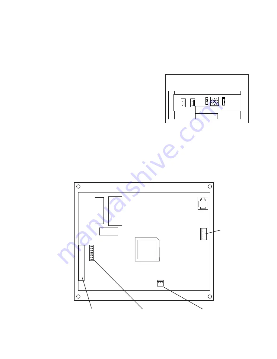
Figure 37.
906G Control Panel connections and
settings.
Figure 38.
Rear view of
the 903 Control Panel.
6-Pin Header
Connection for Model
980EZ System Module
Product Group Expansion Port
34-pin connector for model 904
Product Group ExpanderModule
Configuration DIP Switches
to enable/disable control panel features
3-Pin Header
Connection for Auxiliary IR Sensor
Содержание Access EZ 922
Страница 1: ...Demonstration Network Home Audio and Video System Installation Manual...
Страница 2: ......
Страница 22: ...22 Model 906G Control Panel Model 903 Control Panel Product Select Buttons Custom Third Party Touchscreen...
Страница 32: ...32...
Страница 51: ......


