


XDS-PRO (PRO1R, PRO4R & PRO1S, PRO4S) Satellite Receivers - User Guide Rev. A R830001-2106
7-3
SPECIFICATIONS
ATX
Confi dential & Proprietary
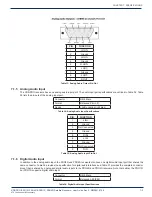
PIN
FUNCTION
1
L OUT+
2
Ground
3
L OUT+
4
Ground
5
R OUT+
6
L OUT-
7
Ground
8
L OUT-
9
R OUT-
Table 33: Analog Audio Output Pin-Out
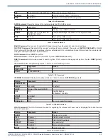
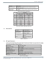
7.1.5 Analog Audio Input
The XDS-PRO receivers have one analog audio input port. The audio input port specifi cations are outlined in Table 34. Table
35 lists the pin-outs of the analog input port.
Connector
DB-9 Male
Format
Balanced Pair L, R
Range
+4dBu nominal (+22max)
Table 34: Analog Audio Input Specifi cations
PIN
FUNCTION
1
L IN+
2
Ground
3
Not Connected
4
Ground
5
R IN+
6
L IN-
7
Ground
8
Not Connected
9
R IN-
Table 35: Analog Audio Input Pin-Out
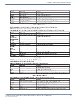
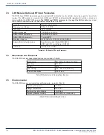
7.1.6 Digital Audio Input
In addition to the analog audio input, the PRO4R and PRO4S receivers also have one digital audio input port that shares the
same connector. Table 36 provides the specifi cation for digital audio interface and Table 37 provides the complete connector
pinout that is shared by analog and digital audio inputs to the PRO4R and PRO4S receivers. Note that neither the PRO1R,
nor PRO1S support a digital audio input.
Connector
DB-9 Male
Format
Balanced AES/EBU
Table 36: Digital Audio Input Specifi cations
CHAPTER 7:


