


XDS-PRO (PRO1R, PRO4R & PRO1S, PRO4S) Satellite Receivers - User Guide Rev. A R830001-2106
3-3
FRONT PANEL OPERATIONS
ATX
Confidential & Proprietary
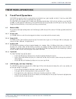
3.3.1 Main Menu Options
Note: For all of the following subsections, please refer to the Front Panel Flow as shown in Figure
1 - PRO Receiver Front Panel Flow.
When the receiver’s front panel is not being used, the idle screen featuring the company
1
logo will be displayed. There are
two important statistics displayed on this front logo screen: EB,
energy per bit relative to noise floor
, which is a quantitative
measure of signal quality; and AG,
automatic gain
, which is an indicator of the signal level. Both of these quantities serve to
describe the quality of the satellite signal and should be used as a guide when positioning the satellite dish. Better signals
have better separation between the data and noise floor, and thus a higher EB. EB range is 0 - 15. Levels above 15 will be
displayed as “>15”. The receiver will fade in and out below 5 dB E
b
/N
0
, and lose lock completely at around 3.5 dB. A powerful
signal will have a high AG (indicating little amplification is required) while a weak signal will have a low AG (indicating unit is
amplifying signal).
Once the ▼ button is pressed, the receiver will navigate into its main menu options. These options are:
•
STATUS
•
SETUP
•
AUDIO PORTS
Continually pressing ◄ (or ►) will cycle through these three main menus. Pressing ▼ or
SET
will navigate into whichever one
of these three options happen to be currently selected.
3.3.2 Status Sub-Menus
From the Status menu, the user can navigate through five sub-menus, each of them offers various status-related information.
From any of these sub-menus pressing the ▲ button will bring you back to the main menu options. The different sub-menus
available in Status are:
•
ACTIVE FAULTS: Describes any active faults that may be affecting the receiver.
•
FAULT HISTORY: Offers a list of past faults which may have occurred. Pushing
3
will clear the fault history.
•
ENVIRONMENT: Indicates whether the internal fans are functioning inside the unit, and the internal temperature of
the receiver unit.
•
POWER STATUS: Readings on the various voltage levels inside the receiver.
•
STORAGE STATUS: Gives an indication of the internal storage drive usage in the receiver. Also gives the option to
“Fix” storage.
3.3.3 SETUP Sub-Menus
By navigating from the Main Menu to Setup, the user reaches the Setup sub-menus. The different sub-menus available under
Setup are:
•
SERIAL NUMBER: Displays the receiver’s serial number. Pressing the
3
quick key underneath “PWD” will display
your receiver’s affiliate site password.
•
M&C PORTS: Displays M&C port settings.
•
IP Only Mode: Refer to Section 2.5.8 on setting up IP Only Mode.
•
NETWORK: Pressing the ▼ will navigate into the Network sub-menus.
•
USB: Pressing the ▼ will navigate into the USB sub-menus.
•
ALARMS: Allows you to set the alarm mask as a hex value.
•
VERSION: Pressing
SET
in this menu will display the receiver’s firmware version.
•
FACTORY DEFAULTS: Pressing
SET
will offer you the option of resetting the receiver’s settings to factory defaults.
Press
1
to confirm or
3
to cancel. Reboot is required.
•
REBOOT: Pressing
SET
will offer you the option of rebooting the receiver or gracefully shutting down the receiver.
Press
1
to reboot,
2
to shut down gracefully,
3
to cancel. (Hot tip: press
3
three times from the top idle screen to
automatically go to this screen).
•
RELAYS: Allows you to switch any of the individual relay signals on Relay A or B to on. Press ▼ to choose which
Relay port to edit, then press
SET
to modify which pins on the relay are activated. A ‘0’ is an un-activated relay and a
‘1’ is an activated relay. The first position is the Relay 1, the second position is Relay 2, and so on.
•
Test Tones: Supply test tones from the receiver.
•
TUNER 1 & TUNER 2: Pressing the ▼ will navigate into the Tuner sub-menus.
CHAPTER 3:
1
The company logo may be replaced by your broadcaster’s logo.


