background image

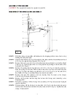
Fig. 4 

ASSEMBLY PROCEDURE   

CAUTION:

 This equipment requires two people to assemble. 


MOUNTING THE SWING ARM ASSEMBLY 


STEP 1:


With the swing arm assembly still attached to the shipping pallet, remove the tie wrap 

holding the lock plate tight.   

STEP 2:


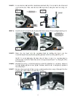
Slide the Hex Shaft (120, Fig.4) through the lock plate until the Mount/Demount head 

(123, Fig. 4) is against the swing arm (119, Fig. 4). 

STEP 3:


Remove the lock cover (116, Fig. 4) from the parts box and slide it over the Hex Shaft 

(120, Fig. 4). Carefully place the cover into position by pushing it onto the tabs of the 

lock plate (107, Fig.4). 

STEP 4:


Remove the spring, Knob Cap and screw (117,115, 114, Fig. 4) from the parts box. 

Place the spring over the Hex Shaft so that it fits all the way down onto the lock plate 

(118, Fig. 4). Place the Knob cap and screw (115, 114, Fig. 4) on to the end of the 

Hex Shaft (120, Fig. 4) and thread the screw into the hex shaft.   

STEP 5:


Remove the nuts, flat washers, and lock washers from the studs on the chassis 

(128,129, Fig. 4) and set them aside. 

STEP 6:


Remove the lag bolts and the strap that secures the Swing Arm Assembly to the 

shipping pallet. 

STEP 7:


With able assistance, lift the Swing Arm Assembly (101 Fig.4) and stand it upright 

onto the machine. 

STEP 8:


With assistance, lift the Swing Arm Assembly (101 Fig.3) onto the studs and secure 

with the nuts flat and lock washers from the studs (128,129, Fig. 4). Tighten the nuts 

using a 16mm wrench. 

Содержание TC589X

Страница 1: ...1 ...

Страница 2: ...Link Up Electric Link Up Warning Label 13 Operating Instructions 14 To Perform Preliminary Operating Texts How to Break the Tire Bead Demounting the Tire from the Wheel Mounting the Tire onto the Wheel Rim Inflating the Tire FRL Instructions 20 Routine Maintenance 21 Troubleshooting Guide 22 Mounting Head s Angle Adjusting 23 IP Version 24 Exploded Drawings And Spare Parts List 29 Electric Schemat...

Страница 3: ...Pressure 145 PSI 10 bar Bead Breaker Force 5500 LB 2500kgs Max Rotating Torque Turntable 795 ft lbs 1078N m Noise Level 70dB Overall Dimensions L W H 60 60 84 1524mm 1524mm 2146mm Net Weight 675Lbs 306kg THE MANUFACTURER RESERVES THE RIGHT TO CHANGE PRODUCT SPECIFICATIONS WITHOUT NOTICE PICTURES OF PRODUCTS IN PICTORIAL GUIDE MAY NOT BE PICTURES OF THE ACTUAL PRODUCT RECEIVED GENERAL OUTLINED ASSE...

Страница 4: ...AIR WILL CEASE AS THE COMPRESSED AIR IS PURGED FROM THE SYSTEM USE COMMON SENSE 2 ALL REPAIR WORK SHOULD BE PERFORMED BY A QUALIFIED MECHANICALLY INCLINED PERSON ANY COMPETENT PERSON THAT IS ABLE TO UNDERSTAND WRITTEN AND SPOKEN ENGLISH INSTRUCTIONS SHOULD BE ABLE TO INSTALL AND SERVICE THIS MACHINE IF YOU ARE NOT MECHANICALLY INCLINED PLEASE EMPLOY A PERSON WITH MECHANICAL SKILLS TO HELP INSTALL ...

Страница 5: ...re changer Counterfeit parts or accessories may result in damage to the machine wheel tire assembly or personal injury Authorized parts are only available from your distributor 11 PERIODIC MAINTENANCE SHOULD BE PERFORMED AT REGULARLY SCHEDULED INTERVALS Daily inspection of the machine and a weekly maintenance schedule will keep your machine working at optimal performance Maintenance should be perf...

Страница 6: ...IR SUPPLY LINE THIS WILL HELP TO PROVIDE SUFFICIENT LUBRICATION TO THE MOVING PARTS AND SEALS 4 ALWAYS INFLATE THE TIRE TO THE AIR PRESSURE RECOMMENDED BY THE TIRE MANUFACTURER NEVER OVER INFLATE THE TIRE 5 MAKE SURE THAT THE TIRE AND RIM SIZE ARE A PERFECT MATCH SEVERE PERSONAL INJURY WILL RESULT IF THE TIRE SIZE AND RIM SIZE ARE DIFFERENT AND THE INFLATED TIRE BLOWS OFF THE RIM WHEN INFLATED ALW...

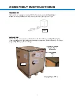
Страница 7: ...machinery capable of safely moving this heavy package See Fig 1 UNPACKING The tire changer is shipped in a palletized wooden box with easy opening tabs Fig 2 Please use the easy opening tabs when uncrating the machine rather than destroying the box and possibly damaging the tire changer Fig 1 Fig 2 ...

Страница 8: ...GULATOR OILER 12 BEAD BREAKER PADDLE 13 RUBBER WHEEL SUPPORT 14 TIRE TOOL WORK AREA REQUIREMENTS You will need a work radius of about 3 feet around the machine to operate your tire changer effectively Place the tire changer on a level concrete floor It must be off of the shipping pallet The tire changer may be bolted to the concrete floor but it is not required The tire changer must be removed fro...

Страница 9: ...g Knob Cap and screw 117 115 114 Fig 4 from the parts box Place the spring over the Hex Shaft so that it fits all the way down onto the lock plate 118 Fig 4 Place the Knob cap and screw 115 114 Fig 4 on to the end of the Hex Shaft 120 Fig 4 and thread the screw into the hex shaft STEP 5 Remove the nuts flat washers and lock washers from the studs on the chassis 128 129 Fig 4 and set them aside STE...

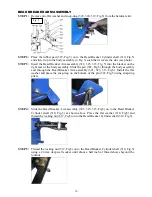
Страница 10: ...2 Fig 5 through the body assembly and through the Bead Breaker Arm assembly 321 323 315 Fig5 Install the flat washer and place the snap ring on the bottom of the pin 322 Fig 5 using snap ring pliers STEP 4 Slide the Bead Breaker Arm assembly 321 323 315 Fig5 on to the Bead Breaker Cylinder shaft 310 Fig 5 as shown above Place the flat washer 318 Fig5 and thread the locking nut 317 Fig5 on to the B...

Страница 11: ...ly pivot bolt Insert the brake tool into the hole near the rear of the Bead Breaker Arm 322 Fig 5 Hook the spring with the tool 330 Fig 5 and pull it toward you Attach the spring 330 Fig 5 on to the center of the pin found within the Bead Breaker Arm See photo below PNEUMATIC Fig 6 IP60 A 1 6 4 5 2 3 7 8 9 ...

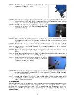
Страница 12: ... screws 10 Fig 6 STEP 8 Press the 8mm tubing from the top of the inflator post A Fig 6 into the push lock fitting at the base of the pressure reading gauge STEP 9 Press the 8mm tubing from the bottom of the inflator post into the push lock bulkhead fitting on the back of the tire changer See photo STEP 10 Connect the tire changer to a compressed air network Suggested supply pressure is 150psi The ...

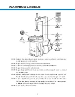
Страница 13: ...ds free of wheel your hands could be crushed between the rim and the mounting head CJ006 Danger During bead breaking NEVER touch the sidewalls of the tire with your hands Bead breaking with the table top slides open can crush the operator s hands CJ007 Caution Bead breaking must be done with the utmost care and attention When the bead breaker pedal is operated the bead beaker arm moves quickly and...

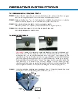
Страница 14: ...fore you attempt to break the bead the tire must be deflated fully This can be done by removing the valve core and allowing all the air to escape Remember that old tire wheel assemblies and junk yard rims require special considerations The bead breaker system is very powerful but certain older rims may have been galled to the tires and it may be difficult for these beads to be broken Rust penetrat...

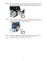
Страница 15: ... Depress the bead breaker pedal fully to activate the paddle Fig 5 Release pressure on the bead breaker pedal when the blade has reached the end of its travel and or when the tire bead becomes free of the rim Broken STEP 4 Rotate the tire slightly and repeat the procedure around the entire circumference of the wheel rim until the bead is completely detached from the rim Fig 5 STEP 5 Repeat the abo...

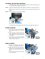
Страница 16: ...oceed as follows according to the wheel size OUTSIDE CLAMPING 1 Position the four jaws by depressing the jaw clamping pedal Fig 7 halfway down 2 Place the wheel on the four jaws and while keeping the wheel rim pressed down depress the jaw clamp pedal as far as it will go 3 As the jaws move in they will lock the wheel Check to make sure the wheel is firmly secured by the jaws INSIDE CLAMPING 1 Oper...

Страница 17: ...mount demount head and briefly pushing upward on the reverse pedal Fig 13 NOTE To avoid damaging the inner tube if there is one it is recommended to perform step 7 with the inner tube valve stem positioned about 1 to the right of the mounting head STEP 6 With the lever Fig 13 held in position rotate the turntable in a clockwise direction by fully depressing the reverse pedal Continue until the tir...

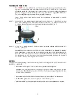
Страница 18: ...ary to lock and unlock the hex shaft Instead move the swing arm sideways with the hex shaft locked STEP 3 Move the tire so that the bead passes below the front section of the mounting head and is brought up against the edge of the rear section of the mounting head See Fig 17 Keep the tire bead pressed down into the wheel rim channel with your hands Fig 18 Keep hands clear of the mounting head Then...

Страница 19: ...er down to lock onto the valve stem Remember to inflate the tire with brief jets of air checking the air pressure frequently Once the proper air pressure has been reached on the gauge disconnect the nozzle from the valve stem and screw a valve core into the stem Use caution when inserting the valve core air will blow out of the stem when the nozzle is removed Re attach the nozzle and adjust the ai...

Страница 20: ...pull up the knob and turn to adjust the air pressure Set air pressure at 110 to125psi Close Push down the knob to lock the regulator when the correct air pressure is achieved pressure The air filter separates water from the air as the air flows into the machine When the water level reaches 50 of the glass bowl it is necessary to drain the water by pulling the locking ring and venting the water Che...

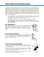
Страница 21: ...in Chapter 7 After the first week of use check all screws bolts and fittings Make sure all screws are tight Turntable slide blots are subject to constant movement and need to be tightened regularly BELT MAINTENANCE If the turntable begins to lose power the drive belt may be loose Remove the side cover of the tire changer to check the belt If the belt is loose tighten the belt with the adjusting sc...

Страница 22: ...inder with gaskets Leaking air fittings Correct air leak replace fitting if necessary PROBLEM 5 Mounting Head touches the wheel rim during tire mounting demounting process Causes Solutions Locking slide for hex shaft is incorrectly adjusted or defective Adjust or replace locking slide Locking slide for hex shaft screw is loose Tighten screw See section 10 for head adjustment PROBLEM 6 Bead Breaker...

Страница 23: ... Lower the hex shaft 7 Fig3 until the mounting head 6 Fig3 rests next to the wheel rim and on top of the wheel Move the locking lever back to lock the hex shaft The mounting head will rise up approximately 2mm STEP 4 Loosen the adjusting screws on the side of the mounting head STEP 5 Adjust the angle of the mounting head by hand Maintain 2mm clearance from the edge of the wheel STEP 6 Tighten the ...

Страница 24: ...will not seat properly by just pumping air through the valve stem Even with the valve core removed The bead blaster system of the modern tire changer takes the place of the spray ether and a match technique used by tire people with no regard for their own safety See movie clip below All tire changer bead blaster systems operate in the same basic way but the Atlas and Coseng tire changers utilize a...

Страница 25: ...maintains the pressure against both beads forcing them to seat permanently and allowing the tire to be inflated to the correct pressure BEAD SEATING AND INFLATING WARNING A WHEEL TIRE ASSEMBLY CAN EXPLODE causing death injury or damage WHEN THE FOLLOWING OCCUR The diameter of the rim is different from the tire size The rim or tire is defective The recommended inflation pressure is exceeded during ...

Страница 26: ...released through the air holes located behind the turntable jaws to help seat the bead of the tire You may need to attempt the bead seating process several times before the beads will seat Allow the air tank at the back of the tire changer to fill completely with air before a new bead seating attempt is made STEP 7 Continue to keep the pedal pressed to the middle position to allow regulated air to...

Страница 27: ...27 ...

Страница 28: ...olt M4 20 IP19 PC08 01 1 L union 1 8 IP109 GB T 50 1 Washer φ4 IP20 PC 3T 0803 2 T union IP110 GB T 1337 1 Self locking nut M4 IP21 C2110327 1 Solenoid hose IP111 GB T 70 1 Screw M6 20 IP22 GB T41 4 Nut M6 IP112 GB T 1337 1 Self locking nut M6 IP23 GB T5781 4 Screw M6 IP113 GB T 50 1 Washer φ6 IP24 GB T5781 2 Screw M10 IP114 GB T 70 1 Screw M8 25 IP25 GB T41 2 Nut M10 IP115 GB T 68 1 Screw M8 25 I...

Страница 29: ...29 ...

Страница 30: ...30 ...

Страница 31: ...31 ...

Страница 32: ...32 ...

Страница 33: ...33 ...

Страница 34: ...34 ...

Страница 35: ...35 ...

Страница 36: ...36 ...

Страница 37: ...1 4 111 C2110128 1 Locking block 302 C211010607 1 Washer φ12 112 GB T 41 1 Nut M12 303 C211010603A 1 Bead breaker cylinder casing 113 GB T 78 1 Screw M12 30 304 GB T 1337 1 Self locking nut M12 114 GB T 70 1 Screw M8 40 305 GB T 95 1 Washer φ12 115 C2110132 1 Knob 306 JB1092 1 O ring φ16 116 C2110129 1 Plastic cover 307 GB T 95 1 Washer φ14 117 C2110131 1 Spring 308 JB1092 2 O ring φ180 118 C21101...

Страница 38: ... 20 421 C211011203 1 Pedals shaft 603 C2110141 1 Motor pulley 422 GB T 1337 1 Self locking nut M8 604 GB T 71 1 Screw M6 10 423 GB T95 1 Washer φ8 605 GB T 11544 1 Belt A26 424 C211011219 1 Spacer 606 C2110211 1 Cable switch to motor 425 C211011210 1 Cam connecting rod 607 C2110212 1 Cable switch to capacitor 426 GB T 70 1 Screw M8 50 608 C2110202 1 Capacitor 35μF 427 GB T 41 2 Nut M8 609 C2110213...

Страница 39: ...8 1 V seal 807 200 03 03 1 Filter and pressure reducer lubr 504 C211015207 1 Gear box pulley 808 C2110161 1 Gauge support 505 GB T 41 1 Nut M10 809 GB T 95 2 Washer φ4 506 GB T 1096 1 Key 6 20 810 GB T 819 2 Screw M4 10 507 C211015206 1 Worm screw 811 GB T 41 2 Nut M4 508 GB T 292 2 Bearing 7010 509 C211015202 1 Worm gear shaft 510 C211015201 1 Worm gear ...

Страница 40: ...40 ...

Страница 41: ...41 ...

Страница 42: ...42 ...

Страница 43: ...43 ...

Страница 44: ...44 ...

Отзывы: