10
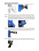
BEAD BREAKER ARM ASSEMBLY
STEP 1:
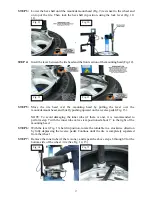
Remove pin, flat washer and snap-ring (322, 320, 319, Fig.5) from the hardware kit.
STEP 2:
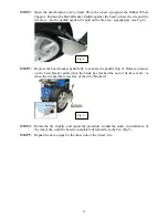
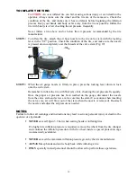
Place the rubber pad (329, Fig.5) on to the Bead Breaker Cylinder shaft (310, Fig.5)
and slide it up to the body assembly (2, Fig.3) such that it covers the slot (see photo).
STEP 3:
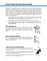
Insert the Bead Breaker Arm assembly (321, 323, 315, Fig. 5) into the bracket on the
right rear of the body assembly. Slide the pin (322, Fig.5) through the body assembly
and through the Bead Breaker Arm assembly (321, 323, 315, Fig5). Install the flat
washer and place the snap-ring on the bottom of the pin (322, Fig.5) using snap-ring
pliers.
STEP 4:
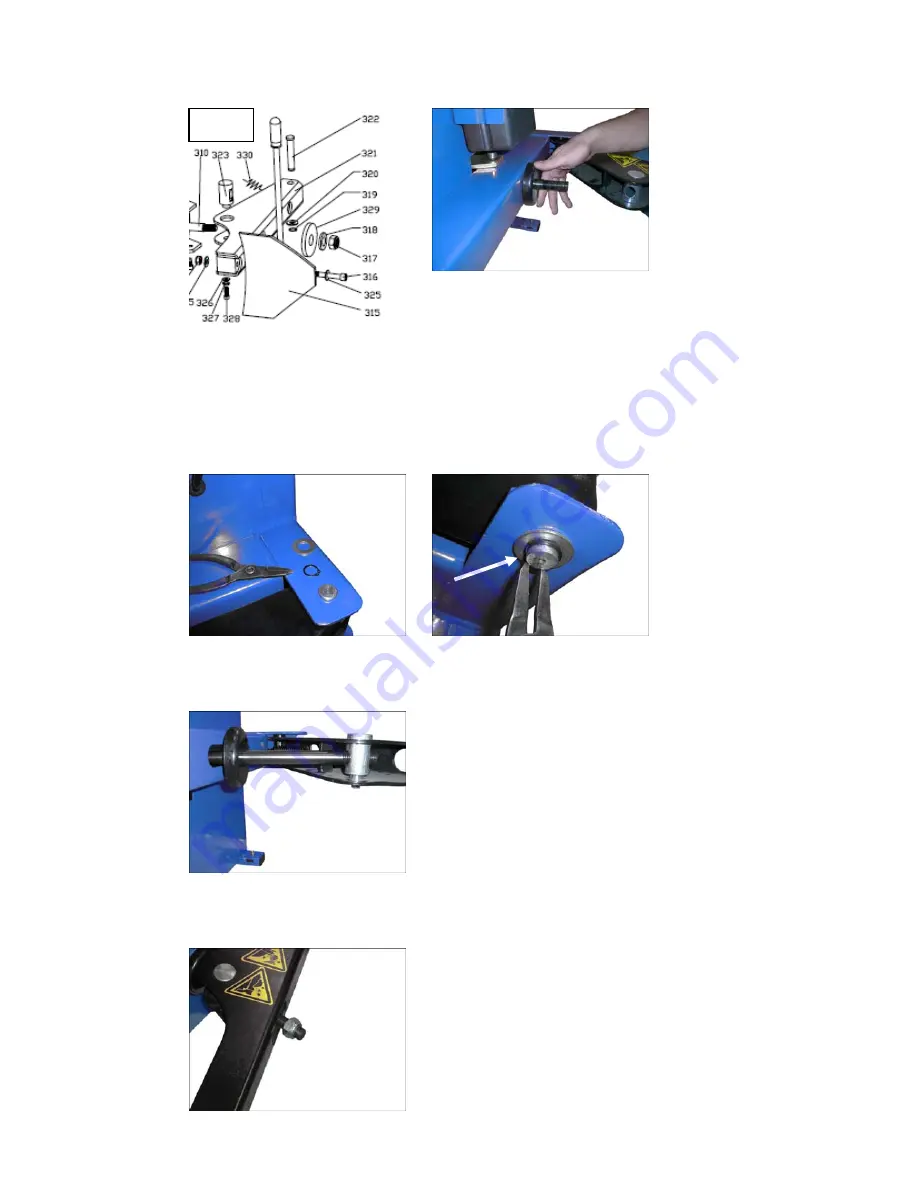
Slide the Bead Breaker Arm assembly (321, 323, 315, Fig5) on to the Bead Breaker
Cylinder shaft (310, Fig.5) as shown above. Place the flat washer (318, Fig5) and
thread the locking nut (317, Fig5) on to the Bead Breaker Cylinder shaft (310, Fig.5).
STEP 5:
Thread the locking nut (317, Fig5) on to the Bead Breaker Cylinder shaft (310, Fig.5)
using a 24 mm deep well socket until about a half inch of thread shows beyond the
locknut.
Fig. 5
Содержание TC589X
Страница 1: ...1 ...
Страница 27: ...27 ...
Страница 29: ...29 ...
Страница 30: ...30 ...
Страница 31: ...31 ...
Страница 32: ...32 ...
Страница 33: ...33 ...
Страница 34: ...34 ...
Страница 35: ...35 ...
Страница 36: ...36 ...
Страница 40: ...40 ...
Страница 41: ...41 ...
Страница 42: ...42 ...
Страница 43: ...43 ...
Страница 44: ...44 ...


