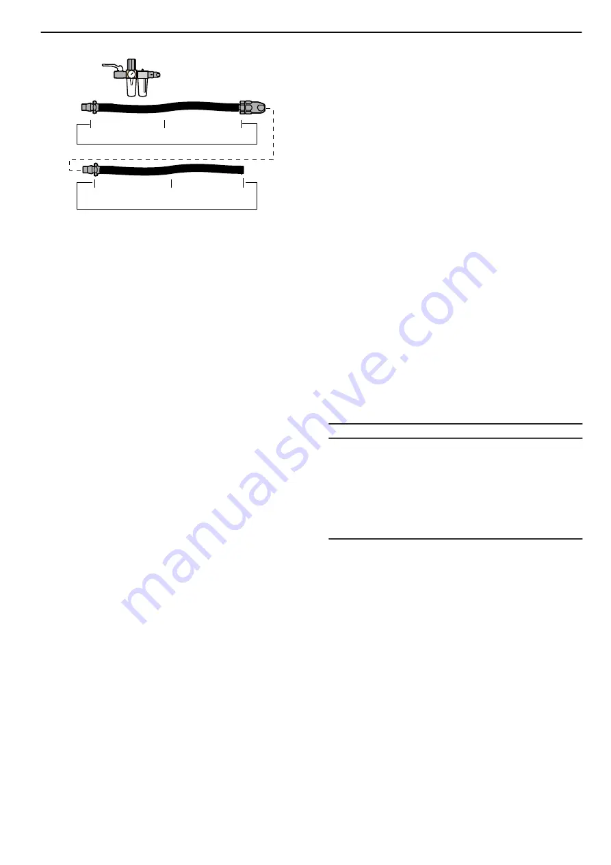
ERGONIP 10 5 m RUBAIR 13
8202 1180 21
ERGONIP 10 0.7 m RUBAIR 13
ERGOQIC 10
8202 1180 21
ip04_1
BALL VALVE+
MIDI F/RD 15+
ERGOQIC 10
8202 0829 11.
For more information, please read Atlas Copco Airline Installa-
tions, Ordering No. 9833 1191 01 or 9833 1025 01.
Handling
Fitting the chisel
Insert the chisel so that chisel retainer (33) snaps into the chisel
groove.Check that the chisel retainer spring is tensioned.
Removing the chisel
Lift the rear end of the chisel retainer (33) and pull the chisel out.
Using the hand guard
The hand guard (41) supplied as an accessory for vibrationdamping
has a snap lock for attachment to the front housing (30).
If it is necessary to guide long chisels near the chisel blade, de-
tach the collet from the machine with a light jerk and move it down
over the chisel.
Attach the collet to the machine before changing chisels.
Avoid holding the chisel directly.
Vibration damping
Vibration damping is accomplished by means of two air springs,
one in the impact mechanism between the piston (23) and thecyl-
inder (22) and one behind the chisel collet ring (28). This latter
spring dampens the shock wave reflex from the chisel. The neces-
sary feed force is determined by the air pressure to the machine.
When the throttle valve is pressed only part of the way in, a lower
speed force is thus required.
For complete vibration damping between the machine housing
(2) and the impact mechanism: Use sufficient feed force so that
the chisel collet ring (28) is pressed up a few millimeters from the
buffer (29), i.e. the chisel is pressed in a corresponing amount into
the front housing.
If the feed force is too high, the chisel collet ring (28) will butt
against the cylinder (22), whereupon vibrations increase noticeably
and the impact effect is reduced.
Idling
When idling, the machine output is appreciably reduced in that
automatic venting occurs via the collet (25). The idling strokes are
absorbed by an elastic buffer (29). When switching from work to
idling, a few individual hard idling strokes may be absorbed via
the buffer.
Avoid unnecessary idling
When the buffer (29) is worn, the chipping hammer may stop
while operating and/or be difficult to start. If this occurs, replace
the buffer immediately in order to prevent harmful blows directly
on the front housing (31).
Maintenance
Overhaul
If the chipping hammer is in daily use, it should be cleaned and
overhauled once every sixth month.
Removal of front housing with chisel retainer and buffer:
1) Disconnect the machine from the compressed air mains.
2) Back off the screw (32) using key (52).
3) Screw the threaded end of key (52) into the hole “A” so that
the front housing (31) is pried apart and can be removed from
the machine casing (2).
4) Remove the buffer (29) with the aid of a screwdriver.
5) Fit a new buffer, making sure that the locking edge snaps into
the groove in the front housing.
6) Before fitting the front housing, check that the chisel collet
ring (28) is fitted with the cone facing towards the sealing ring
(27).
7) Push the front housing onto the machine housing as far as it
will go.
8) Back off and remove the key (52). Fit the screw (32) andn
tighten with a torque of 40 Nm (4 kpm).
Lubrication
During work, oil must be supplied to the chipping hammer once
per shift in an amount of 2.5 ml. The oil is dripped into the air
hose. When the machine is in continuous service, installation of
an Atlas Copco oil—fog lubricator in the compressed air line is
recommended.
Always use lubricants of good quality. The oils and greases
mentioned in the chart are examples of lubricants which are recom-
mended.
Grease guide
Air lubrication
Grease
Brand
Energol E46
Energrease LS-EP2
BP
Arox EP46
Beacon EP2
Esso
Chopin 46
Rembrandt EP2
Q8
Almo Oil 525
Mobilegrease XHP 222
Mobil
Torcula 32
Alvania EP2
Shell
Aries 32
Multifak EP2
Texaco
BR2 Plus
Molycote
Useful information
C
Log in to Atlas Copco www.atlascopco.com
You can find all kind of information concerning Atlas Copco Tools
products, accessories, spare parts, published matters on our WEB
site!
Spare parts
Parts without ordering number are for technical reasons not deli-
vered separately.
The use of other than genuine Atlas Copco replacement parts
may result in decreased tool performance and increased mainten-
ance and may, at the company option, invalidate all warranties.
Warranty
Contact the Atlas Copco sales representative within your area to
claim a product. Warranty will only be approved if the product
has been installed, operated and overhauled according to the oper-
ating instructions delivered with the tool.
Please also see the delivery conditions applied by the local Atlas
Copco company.
5
Atlas Copco Tools - 9836 1761 00
Safety and operating instructions
RRD37/57


