Manual, Control Module, PROFINET, DL12
Document #9620-20-C-DL12-06
Pinnacle Park • 1031 Goodworth Drive • Apex, NC 27539 • Tel: 919.772.0115 • Fax: 919.772.8259 •
C-22
8. Connect the 5‑pin power cable and PROFINET cable connectors to the module.
9. Remove the 5 mm set screw from the FE ground terminal using a 3 mm hex key.
10. Connect the ground to the FE grounding terminal using a M5 customer supplied fastener.
11. Set the Tool‑ID. Refer to
Section 3.8—Setting the Tool‑ID.
12. After the procedure is complete, resume normal operation.
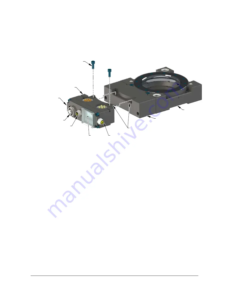
Figure 3.2 —Tool Module Installation
Tool Changer
Valve Adapter on Tool Side
(9121-JR4-T Shown)
Use Ledge Mounting Feature
to Properly Align Module
(2) M6 Socket Head Cap Screw
DL12 Tool Module
Safety Switch Connection
Tool-ID
Power Connection
PROFINET Connection
FE Ground Connection
With M5 Set Screw
(Not Visible)
3.4 Tool Module Removal
Tools required: 5 mm Allen wrench (hex key)
1. Place the Tool in a secure location.
2. Uncouple the Master and Tool plates.
3. Turn off and de‑energize all energized circuits (e.g. electrical, air, water, etc.).
4. Disconnect the safety switch cables from the module.
5. Disconnect the 5‑pin power cable and PROFINET cable connectors from the module.
6. Disconnect the ground from the FE grounding terminal.
7. Set the Tool‑ID. Refer to
Section 3.8—Setting the Tool‑ID
8. Support the module and remove the (2) M6 socket head cap screws and lift up on the module until it
clears the guide pin.
3.5 PROFINET Interface
The PROFINET interface parameters and I/O bitmaps employed in the modules are found in
PROFINET Interface Information
of the manual. These should be thoroughly understood prior to operating
the Tool Changer. A detailed operational sequence is provided in
Section 4.4—Recommended Sequence of
3.6 Utility Schematic
Refer to drawings in
of this manual for customer interface and wiring details for the
Master/ Tool modules.
3.7 Electrical Connections
Refer to drawings in
of this manual for electrical connection and pin/signal
information.


