VP1420 / VP1421 User Manual
23
VPK104
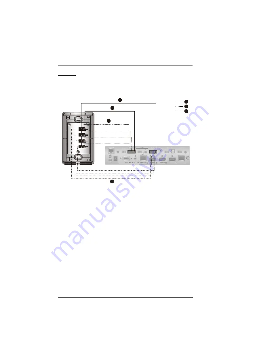
Follow the steps below to safely install the Remote Pad to the VP1420 /
VP1421. Before you start, prepare 2 screws, 1 wall box, and some core wires.
1. (Optional) Prepare your installation site and install a Wall Box.
2. Remove the faceplate from the Remote Pad.
3. Ground the Remote Pad.
a) Use core wires to serially connect the Remote Pad’s LED In (-) poles to
the GND pole of the LED Out terminal on the Presentation Switch.
b) Use core wires to serially connect the Remote Pad’s Contact Out (-)
poles to the GND pole of the Contact In terminal on the Presentation
Switch.
4. Use a core wire to connect the Remote Pad’s LED In Port 1 (+) to the LED
Out pole 1 on the Presentation Switch. Repeat this step for other LED In
Ports.
5. Use a core wire to connect the Remote Pad’s Contact Out Port 1 (+) to the
Contact In pole 1 on the Presentation Switch. Repeat this step for other
Contact Out Ports.
6. Make sure the keys are installed to the VPK104 and then secure the unit to
the wall box using two screws.
3a
4
4
3
5
5
3b
Содержание VP1420
Страница 1: ...4 x 2 True 4K Presentation Matrix Switch VP1420 VP1421 User Manual www aten com...
Страница 18: ...Chapter 1 Introduction 8 This Page Intentionally Left Blank...
Страница 34: ...Chapter 2 Hardware Setup 24 7 Cover the unit with the faceplate 7 6 Wall Box not included Faceplate...
Страница 40: ...Chapter 3 Local Operation 30 This page is intentionally left blank...
Страница 56: ...Chapter 4 Remote Operation 46 This Page Intentionally Left Blank...
Страница 84: ...Chapter 6 Video Presentation Control App 74 VP1420 Audio Input Settings VP1421 Audio Input Settings...
Страница 102: ...Chapter 6 Video Presentation Control App 92 Audio Panel VP1420 Audio Output Settings VP1421 Audio Output Settings...
Страница 108: ...Chapter 6 Video Presentation Control App 98...


