Chapter 3. Front Panel Configuration
19
Main Screen
The Main Screen shows the Input ports in the top row, which are tied to the
Output ports shown in sequential order (1–9) or (1–4) at the bottom row.
The front panel pushbutton label (1–9) or (1–4) corresponds to the
Input
ports and
Output
ports on the unit’s rear panel.
Use the
Menu
pushbutton to view the LCD Menu (see
LCD Menu
Organization
, page 23).
Use the
Profile
pushbutton to switch between profile connections (see
Profile List
, page 41).
Port Switching
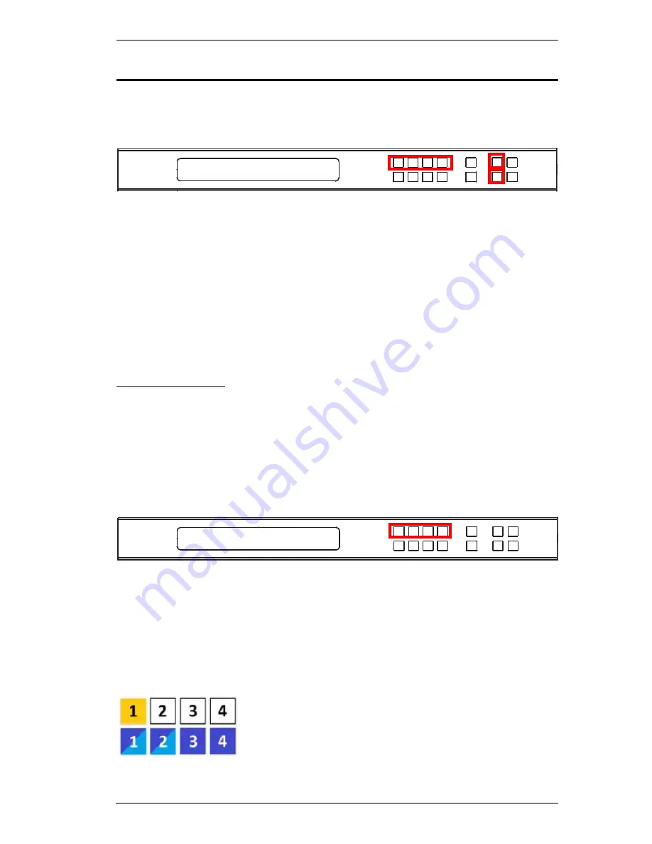
From the Main Screen, users can configure the Input-to-Output port
connections to associate an Input source device to an Output display.
Input Port Selection
Use the Input Port pushbuttons to select the Input
port you want to configure.
To select which input source displays on each output port, do the following:
1. Press any Input port pushbutton (1–9). The Output port LED(s) tied to the
said Input port flash.
In the example below, pressing Input port 1 shows it is tied to Output ports
1
and
2
.
INPUT 1 2 3 4
OUTPUT 1 2 3 4
P1
INPUT 1 2 3 4
OUTPUT 1 2 3 4
Содержание VM3404H
Страница 1: ...4 x 4 9 x 9 HDMI HDBaseT Lite Matrix Switch VM3404H VM3909H User Manual www aten com ...
Страница 25: ...Chapter 2 Hardware Setup 15 Installation Diagram 6 7 1 4 2 9 8 3 2 5 3 1 ...
Страница 26: ...VM3404H VM3909H User Manual 16 This Page Intentionally Left Blank ...
Страница 48: ...VM3404H VM3909H User Manual 38 This Page Intentionally Left Blank ...
Страница 94: ...VM3404H VM3909H User Manual 84 This Page Intentionally Left Blank ...
Страница 100: ...VM3404H VM3909H User Manual 90 edit custom Enter Implements the customized mode Command Control Enter Description ...
Страница 118: ...VM3404H VM3909H User Manual 108 This Page Intentionally Left Blank ...


