


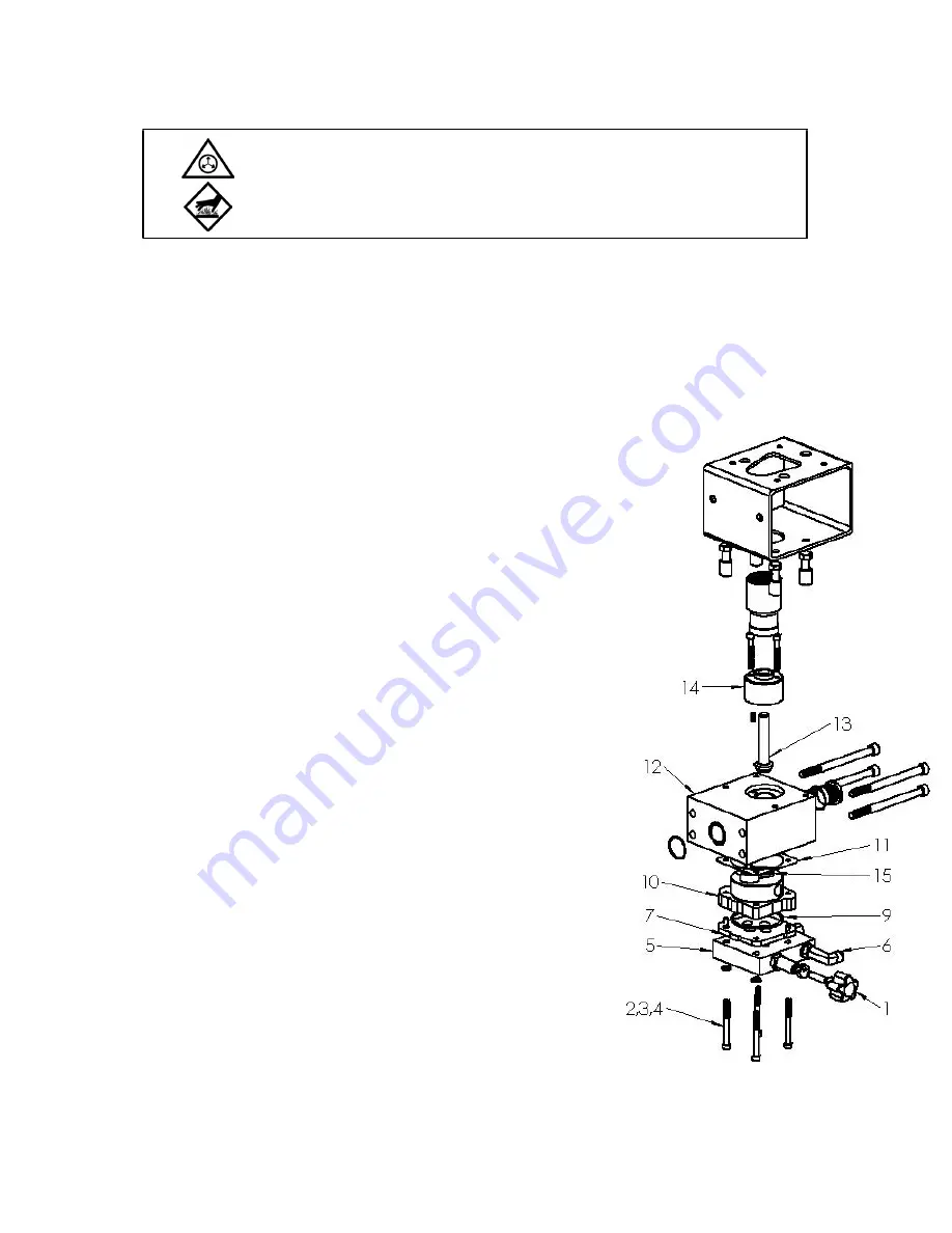
V4 Pump and Flow Control Block Replacement
1. If melt unit is cold, allow to heat for approximately 5 minutes.
2. Depressurize the system by manually actuating the applicator(s).
3. Remove electrical power from the system at the main circuit breaker and at the external source.
4. Disconnect the hose
fl
uid connection(s) from the
fl
ow control block [5]. Disconnect the hose
electrical connection(s) from the bottom of the control box. Set the hose(s) aside.
5. Remove the 4 screws,
fl
at washers and lock washers [2, 3, 4] holding the
fl
ow control block [5].
6. Remove the
fl
ow control block [5], and set it aside. Do not lay the
fl
ow control block
fl
at on any
surface, it may glue itself to the surface.
7. Remove and discard the existing pump [10], gasket [11], wear plate
[8], and pump o-ring [9].
8. Reassemble the pump as follows:
NOTE: V4 pump is shipped with bolts and nuts holding
pump and wear plate together.
a. Remove and discard the bolts and nuts [15] holding the new
pump [10] and wear plate [8] together.
b. Place the 4 screws,
fl
at washers and lock washers [2, 3, 4]
into the
fl
ow control block [5].
c. Cover the new pump o-ring [9] with silicone grease, and
place it into the groove in the pump body.
d. Coat and insert the wear plate o-ring [7] into the groove in
the pump wear plate [8]. Place the pump body [10] onto the
wear plate [8], ensuring not to pinch the o-ring [7].
e. Place the new pump [10] and wear plate [8] into the
fl
ow
control block [5]. Align the assembly with the screws,
fl
at
washers and lock washers [2, 3, 4] so that the bushing
assembly [14] faces away from you and the
fl
ow control
valve faces to the right.
f. Place new gasket [11] on pump [10]. No sealants needed.
9. Align the pump shaft slot on the end of the shaft [13] with the tab
atop the pump [10].
10. Slide the pump assembly into the pump block [12] and tighten the
screws,
fl
at washers and lock washers [2, 3, 4] in a crisscross
fashion.
11. Reconnect hose(s)
fl
uid and electrical connections, and reapply
electrical power to the melt unit.
12. With the pump switch o
ff
, allow the melt unit to heat to operating
temperature.
13. Retighten pump screws to 5.65 – 8.47 N-m (50 – 75 Ibs.-in.).
14. Adjust the adhesive pressure by turning the
fl
ow control knob [1].
Refer to Section 4.2 Adjustments.
15. Test the melt unit, adjust the pressure and check for leaks.
16. Return the melt unit to service.
©Astro Packaging Rev D
D2-15 Manual-19600-10-D215
7-8
WARNING:
Contents at high temperature and pressure. Remove pressure before opening
fi
lter or drain valve to prevent accidental discharge of system pressure. Do not
touch hot surfaces. Failure to follow these instructions may result in severe burns.
Содержание D2-15
Страница 1: ......
Страница 2: ......
Страница 15: ...Dimensions Astro Packaging Rev D D2 15 Manual 19600 10 D215 2 3 ...
Страница 31: ... Astro Packaging Rev D D2 15 Manual 19600 10 D215 4 11 ...
Страница 48: ... Astro Packaging Rev D D2 15 Manual 19600 10 D215 8 5 ...
Страница 50: ... This page is intentionally left blank Astro Packaging Rev D D2 15 Manual 19600 10 D215 8 7 ...
Страница 52: ... Astro Packaging Rev D D2 15 Manual 19600 10 D215 8 9 ...
Страница 54: ... Astro Packaging Rev D D2 15 Manual 19600 10 D215 8 11 ...
Страница 58: ... This page is intentionally left blank Astro Packaging Rev D D2 15 Manual 19600 10 D215 8 15 ...
Страница 61: ... This page is intentionally left blank Astro Packaging Rev D D2 15 Manual 19600 10 D215 8 18 ...
Страница 64: ...Motor Wiring Astro Packaging Rev D D2 15 Manual 19600 10 D215 9 3 ...
Страница 65: ...Wiring Diagram 120V Astro Packaging Rev D D2 15 Manual 19600 10 D215 9 4 D200113 ...
Страница 66: ...Wiring Diagram 240V Astro Packaging Rev D D2 15 Manual 19600 10 D215 9 5 D200113 ...
Страница 67: ... This page is intentionally left blank Astro Packaging Rev D D2 15 Manual 19600 10 D215 9 6 ...


