


AS64 series AC servo drive Commissioning
-245-
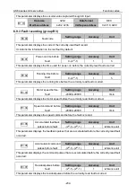
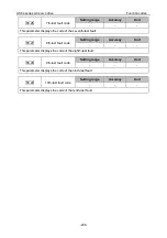
The common procedure for adjusting parameters in speed mode is as follows:
1. Restore default settings.
For details, see section 5.2.5.3 "Factory parameter restoring".
2. Adjust the torque smoothing filter.
If the analog input is a torque command, you can adjust the torque smoothing filter to smooth the
torque change.
3. Set the frequency division for feedback pulse output.
If the encoder feedback pulse signal needs to be output, you can set the frequency-division output
coefficient parameters P0.06 and P0.07 to change the pulse output frequency.
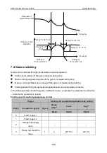
7.3 Mechanical resonance suppressing
The mechanical system resonates at a certain frequency. If a high servo response speed is set when
the mechanical rigidity is low, the shaft torsion may cause resonance (including vibration and abnormal
noise) near the mechanical resonant frequency. At this situation, you can set notch filter parameters
to effectively suppress mechanical resonance.
A notch filter can suppress the mechanical resonance peak by reducing the gain at certain frequency.
You can set notch filter parameters to suppress the resonant frequency, width, and depth, so as for
the system to obtain higher gains or reduce vibration.
The servo drive has been equipped with four notch filters, which are specified by the first notch filter
parameters P1.23, P1.24, and P1.25, second notch filter parameters P1.26, P1.27, and P1.28, third
notch filter parameters P1.29, P1.30, and P1.31, and fourth notch filter parameters P1.32, P1.33, and
P1.34 respectively.
Note:
The notch filters are a lagging factor for the servo system. If the center frequency of a notch
filter is incorrectly set or the suppression depth is too large, the vibration may be stronger. You are
recommended to gradually increase the depth (the parameter setting changes from large to small)
until requirements are met.
The relationship between the Q factor, width, and depth of a notch filter is as follows:
⚫
Q factor of notch filter = Center frequency of notch filter/Bandwidth of notch filter
⚫
The width of the notch filter indicates the frequency difference between the -3dB–dropped power
spectrums at the two sides of the center frequency when the depth of the notch filter is 0.
⚫
The depth of the notch filter indicates the ratio of input to output. The power spectrum strength is
attenuated by 20 log(P1.25%, P1.28%, P1.31%, P1.34%) dB.


