


AS64 series AC servo drive Function codes
-110-
P1.20
Data size
16bit
Data format
DEC
Modbus address
1240, 1241
CANopen address
0x2114, 0x00
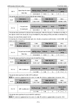
P1.21*
Mechanical
resonant frequency
1
Setting range
Default
Unit
Applicable
mode
0–5000
5000
Hz
P
S
T
P1.22*
Mechanical
resonant frequency
2
Setting range
Default
Unit
Applicable
mode
0–5000
5000
Hz
P
S
T
This group of parameter displays mechanical resonant frequency. When P1.20 is set to 1,
indicating mechanical resonance frequency detection is valid, the system detects and displays the
frequency at the maximum resonance point.
Note:
⚫
The measurement results are accurate only when the rotation speed reaches 30 r/min at least.
⚫
This function is read only. You can set the notch filter frequency through this group of parameter
to eliminate mechanical resonance.
⚫
The value 5000 indicates no resonance point is found.
P1.21
Data size
16bit
Data format
DEC
Modbus address
1242, 1243
CANopen address
0x2115, 0x00
P1.22
Data size
16bit
Data format
DEC
Modbus address
1244, 1245
CANopen address
0x2116, 0x00
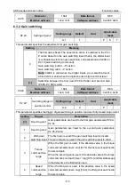
P1.23
Frequency of notch
filter 1
Setting range
Default
Unit
Applicable
mode
50–5000
5000
Hz
P
S
T
This parameter specifies the frequency of notch filter 1 for suppressing resonance. The notch filter
can simulate the mechanical resonant frequency, thus suppressing the resonant frequency.
The value 5000 indicates the notch filter function is invalid.
P1.23
Data size
16bit
Data format
DEC
Modbus address
1246, 1247
CANopen address
0x2117, 0x00
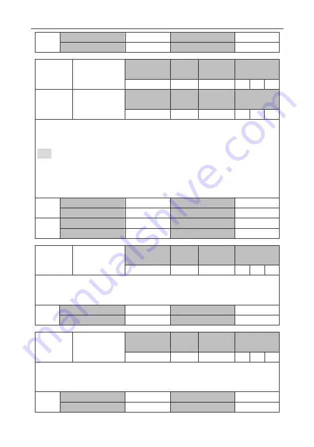
P1.24
Q factor of notch
filter 1
Setting range
Default
Unit
Applicable
mode
0.50–16.00
1.00
-
P
S
T
This parameter specifies the quality factor (Q factor for short) of notch filter 1.
Q factor of notch filter = Center frequency of notch filter/Bandwidth of notch filter
Generally, the default value is kept.
P1.24
Data size
16bit
Data format
DEC
Modbus address
1248, 1249
CANopen address
0x2118, 0x00


