28
EN
Installation and connection
Wire-interconnected interlock (1385)
Note!
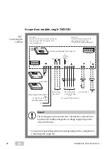
Escape route securing according to the fail-unlocked principle:
If the power
fails or is switched off, all doors are unlocked and can be opened at the same time.
Function
The example describes a basic interlock door system with an emergency exit
function without a central bus master (stand-alone operation).
If a door is temporarily unlocked or unlocked, the corresponding door or several
doors are blocked. The locked doors cannot be opened.
If the disengaged door is not opened before the pre-set temporary release
interval has elapsed, it is automatically locked again.
Prerequisites
· The
escape door terminal
1385
must be set to
master
in stand-alone operation
(“DIP switch 1”, page 18).
·
Profile 3
must be set on
I/O extensions 901–20
(“I/O extension module 901-20”, page 24).
Function
Description
Output functions (A1 to A4)
Block interlock. The corresponding opposite
door(s) is/are blocked.
Output function K1 and K2
'Door blocked' and 'Door closed and locked'
indicator displays.
Input function E1
Central release (for opening interlock in the
event of a fault). The door is released central-
ly and a corresponding alarm is triggered.
Input functions (E2 to E8)
Block door.
I
ON
8
7
6
5
4
3
2
1
OFF
Tab. 8:
Functions of I/O
extensions 901–20
Содержание 1384
Страница 13: ...13 EN Assembly and connection ...
Страница 17: ...17 EN Assembly and connection Fig 4 Replacing the profile half cylinder 3 0 5 180 2 3 3 0 5 5 4 1 ...
Страница 62: ...62 EN ...
Страница 63: ...63 EN ...


