19
EN
Installation and connection
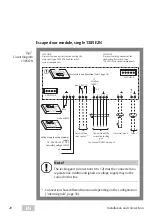
Escape door module, individual, 1384E2N
Fig. 6 :
Circuit diagram
1384E2N
2
1
3 4
5 6 7
8 9
11 12
10
13 14
15 16
A B
E
D
F
S
Voltage supply external power
supply
12 - 24 VDC +15% / -15%
Low safety voltage (SELV)
Connection of the
respective locking
part
SYSCON-5
SYSCON-4
max. 30 V / 1A
Potential-free
relay contact
1)
Universal
input
1)
See manual D00470 manual.
+
–
SYSCON 5:
5-pin system plug connector for
connecting key switch type
1385ES1/ES3 or other components
2
1
ON
OFF
BMS
2
1
ON
OFF
2
1
ON
OFF
without BMS
A
SYSCON 4:
4-pin system connectors for connecting the
mains part type 1003FT-24 and/or other
system components
F1
Littelfuse
154001
1AF
Master-slave configuration (Tab. 1 page 18)
1)
Connections have different functions depending on the configuration
(“Alarm signals”, page 35).
Note!
The locking part (connections 8 to 12) must be connected in a
separate line. Additional signals or voltage supply may not be
carried in this line.
A
Содержание 1384
Страница 13: ...13 EN Assembly and connection ...
Страница 17: ...17 EN Assembly and connection Fig 4 Replacing the profile half cylinder 3 0 5 180 2 3 3 0 5 5 4 1 ...
Страница 62: ...62 EN ...
Страница 63: ...63 EN ...


