background image

57

EN

Technical data, maintenance

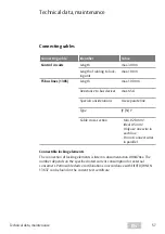
 Connecting  cables

Connecting cable

Identifier

Value

Control circuits

Length

max. 300 m

Length of cabling to lock-
ing unit

max. 100 m

TS bus lines (1385)

Length

max. 1000 m

Resistance to bus devices

max. 65 Ω

Special considerations

Use separate line

Type

JY (St) Y

Cable cross-section

 · Min. 0.28 mm²

Ideal 0.5 mm²

 · Only use one wire in 

each line

 · Do not connect wires 

in parallel

Connectible locking elements

The connection of locking elements is listed in documentation D00470xx. The 
number depends on the specified rated current consumption for external 
consumers. Permissible device combinations in accordance with EltVTR/DIN EN 
13637 can be found in the current test certificate.

 Technical data, maintenance

Содержание 1384

Страница 1: ...XXXXXNN Installations und Montageanleitung Produktname Produktname www assaabloy com de Experience a safer and more open world Installation and mounting instructions Escape route technology D0133500 Escape door control terminal Type 1384 1385 ...

Страница 2: ...s parts are copyrighted Any use or changes outside the strict limits of the copyright are prohibited and liable to prosecution unless prior consent has been obtained from ASSA ABLOY Sicherheitstechnik GmbH This particularly applies to any copying translations microforms or storing and processing in electronic systems Test logbook https aa st de file d01350 Sicherheitstechnik GmbH Werk Albstadt Elt...

Страница 3: ... 16 Installation and connection 18 View of circuit boards 18 DIP switch 1 18 DIP switch 2 18 Escape door module individual 1384E2N 19 Escape door module single 1385E2N 20 Key switch module 1385ES1 21 Individual 21 Parallel 21 Key switch module 1385ES2 ES3 22 Individual 22 Parallel 22 Key switch module 1380E04 23 Individual 23 Parallel 23 I O extension module 901 20 24 Profiles and pin assignment o...

Страница 4: ...alarm 36 Acknowledge an alarm and see the cause of the alarm 36 Cause of alarm 37 Displaying cause of alarm 37 Acknowledging an alarm 38 Acknowledge several alarms and display alarm causes 38 Configuration 39 General 39 Configuration 40 Switch on configuration mode 40 Menu on key switch 41 Menu levels 41 Advancing through menu items 41 Defining settings in the menu 41 Configure times 42 Procedure ...

Страница 5: ...hort circuit 54 Short circuit is displayed 54 Completing a configuration 55 Ending configuration mode 55 End configuration mode automatically 55 Example configuration 56 Starting configuration mode 56 Changing to the Pre alarm time menu 56 Configuring pre alarm time 56 Leaving the configuration menu 56 Technical data maintenance 57 Connecting cables 57 Connectible locking elements 57 Escape door m...

Страница 6: ...stand alone system not integrated into the building network commissioned and configured via key switch without expansion options Escape door control terminal 1385 The escape door control terminal 1385 is offline for a complex individual applica tion stand alone operation for a wire interconnected interlock function commissioned and configured via key switch expandable with the I O module 901 20 Th...

Страница 7: ... with LED status display The Emergency Open push button is pressed in the case of an emergency in order to request a release of the locked escape door An alarm is also triggered in the process Key switch for configuration and release With the key switch the escape door is unlocked and operation is authorised ...

Страница 8: ...basis Further knowledge of the product is required for the subsequent inspection of the correct mounting and installation commissioning and maintenance This does not form part of this manual Meaning of the symbols Danger Safety notice Failure to observe these warnings will lead to death or severe injury Warning Safety notice Failure to observe these warnings may lead to death or serious injury Cau...

Страница 9: ...ng must be performed by a qualified person ASSA ABLOY Sicherheitstechnik GmbH offers training for qualification in the requisite skills Danger due to faulty or improperly performed maintenance The owner is responsible for correct installation and functional inspection of the product and connected components Safe functionality of the mechanical components must be checked at least once a month by th...

Страница 10: ...st be identified A sign pictogram must be affixed on the inside of an electronically controlled door in the escape route This sign must be affixed for identification of the Emer gency Open push button Function failure with incorrect operating voltage at the components A mains adapter according to SELV requirements must be used Separate mains adapters must be connected for the supply of devices wit...

Страница 11: ...ovide the necessary planning informa tion for approved solutions and the device combinations required for your application The usage must be coordinated with the requirements of the building inspectorate Contact the competent building authority for this purpose Compliance with all relevant requirements of the building inspectorate is manda tory for use particularly with respect to the coordination...

Страница 12: ... switch box 6 2 5 6 0 Cable selection The conductor cross section must be selected so that the voltage on the locking part is no more than 10 below the specified rated voltage of the locking part at full load and take into account all other losses such as the voltage drop on the supply line Connecting cables page 57 Supply lines must be fed through holes in the flush mounted switch boxes and fed a...

Страница 13: ...13 EN Assembly and connection ...

Страница 14: ...ssembly and connection Mounting the escape door control terminal Fig 3 Mounting and connecting the escape door control terminal 6 4 3 2 1 5 3 2 1 5 6 7 4 3 2 1 8 10 9 1211 16 15 14 13 1 2 2 5 4 3 6 1 7 8 1 2 3 ...

Страница 15: ... Potential free relay contact 30V 1A Power supply or via SYSCON4 Jumper fire alarm system BMS with fire alarm system DIP switch 2 OFF without fire alarm system DIP switch 2 ON 6 SYSCON4 1385EVL4 5 6 7 4 3 2 1 NO C NC 2 1 ON OFF 2 1 ON OFF with BMS without BMS Key switch module 7 6 4 3 2 1 5 Optional Connection for an external controller 8 SYSCON5 1385EVL5 Illuminated emergency sign optional 1 SYSC...

Страница 16: ...r in place 3 Pull the profile half cylinder out towards the front 3 1 Turn the cam upwards 180 position 3 2 Pull the locking cylinder out towards the front 4 Replace with a suitable new cylinder 5 Secure the cylinder with the fixing screw 6 Check the function of the cam by closing to the left and right 7 Reassemble all components and perform a final functional test You have replaced the profile ha...

Страница 17: ...17 EN Assembly and connection Fig 4 Replacing the profile half cylinder 3 0 5 180 2 3 3 0 5 5 4 1 ...

Страница 18: ...itch 1 is set to OFF at the factory Button Function OFF ON 1 TS bus Master Slave 1385 Slave For stand alone operation without I O extension and networked operation Master with Address 1 For stand alone operation with I O extension IfanI Oextensionisused thismustbeassignedtoaddress 2 DIP switch 2 DIP switch 2 is set to ON at the factory For setting DIP switch 2 see Fig 6 page 19 and Fig 7 page 20 T...

Страница 19: ...SYSCON 5 5 pin system plug connector for connecting key switch type 1385ES1 ES3 or other components 2 1 O N O F F BMS 2 1 O N O F F 2 1 O N O F F without BMS A SYSCON 4 4 pin system connectors for connecting the mains part type 1003FT 24 and or other system components F1 Littelfuse 154001 1AF Master slave configuration Tab 1 page 18 1 Connections have different functions depending on the configura...

Страница 20: ...385ES1 ES3 or other components 2 1 O N O F F without BMS A Voltage supply external power supply 12 24 VDC 15 15 Low safety voltage SELV 2 1 O N O F F 2 1 O N O F F SYSCON 4 4 pin system connectors for connecting the mains part type 1003FT 24 and or other system components F1 Littelfuse 154001 1AF Master slave configuration Tab 1 page 18 1 Connections have different functions depending on the confi...

Страница 21: ...diagram 1385ES1 SYSCON 5 1 1 2 2 3 3 4 5 L R SYSCON 5 1 1 2 2 3 3 4 5 L R 1 3 2 1 3 2 1385EVL5 Tampering Tamper JP1 Tampering Tamper JP1 SYSCON 5 1 1 2 2 3 3 4 5 L R 1385EVL5 Tampering Tamper JP1 1 3 2 A A A Max 24 V 100 mA Max 24 V 100 mA Max 24 V 100 mA Individual Parallel ...

Страница 22: ...gram 1385ES2 ES3 SYSCON 5 1 1 2 2 3 3 4 5 L R SYSCON 5 1 1 2 2 3 3 4 5 L R 1 3 2 1 3 2 1385EVL5 Tampering Tamper JP1 Max 24 V 100 mA Tampering Tamper JP1 SYSCON 5 1 1 2 2 3 3 4 5 L R 1385EVL5 Tampering Tamper JP1 1 3 2 6 6 6 Max 24 V 100 mA Max 24 V 100 mA A A A Individual Parallel ...

Страница 23: ...1380E04 Fig 10 Wiring Diagram 1380E04 SYSCON 5 9 10 11 12 13 14 1 2 3 4 5 1 3 2 SYSCON 5 9 Jumper Remove 10 12 10 11 12 13 14 1 2 3 4 5 1 3 2 9 10 11 12 13 14 1 3 2 A A A A 1380E04 Escape door module 1380E04 Escape door module 1380E04 Individual Parallel ...

Страница 24: ...e drop K1 Potential free relay output Max load capacity 24V 2A ohmic load K2 Potential free relay output Load capacity max 24V 2A resistive load Only one power supply may be connected A A 12 V DC 10 residual ripple 50 Only on terminals 1 and 2 24 V DC 10 regulated OFF 12 V battery or 12 V DC regulated 1 2 3 4 5 6 7 8 9 10 11 12 13 14 15 16 17 1819 20 21 22 23 24 25 26 27 28 12345678 ON OFF F1 0 5A...

Страница 25: ...module 1385 Master slave configuration TS Bus 1385 see Tab 1 page 18 Note When configuring using FT Manager select the correct profile If configuration is carried out using FT Manager Profile 0 Function templates in FT Manager must be selected as changes are only saved there Pro file DIP switch Function page 26ff 3 4 0 OFF OFF Link to higher level systems factory setting 1 OFF ON Door drive 2 ON O...

Страница 26: ...Alarm signal inverse E3 Clock A1 E4 Lock A2 E5 Unlock A3 E6 Release with delay A4 E7 Temporary release E8 Connec tions Description Connec tions Description E1 Fire detector system inverse K1 Door drive Automatic operation E2 Burglar alarm system Interlock K2 Door drive Activation E3 Clock A1 E4 Lock A2 E5 Unlock A3 E6 Release with delay A4 E7 Temporary release E8 Tab 4 Profil 0 Link to higher leve...

Страница 27: ...ock K2 Holding magnet E3 Clock A1 E4 Lock A2 E5 Unlock A3 E6 Release with delay A4 E7 Temporary release E8 Connec tions Description Connec tions Description E1 Fire detector system inverse K1 Door is interlocked E2 Burglar alarm system interlock K2 Door is closed and locked inverse E3 A1 Block interlock E4 A2 E5 A3 E6 A4 E7 E8 Tab 6 Profile 2 Door drive Tab 7 Profile 3 Interlock ...

Страница 28: ...pened before the pre set temporary release interval has elapsed it is automatically locked again Prerequisites The escape door terminal 1385 must be set to master in stand alone operation DIP switch 1 page 18 Profile 3 must be set on I O extensions 901 20 I O extension module 901 20 page 24 Function Description Output functions A1 to A4 Block interlock The corresponding opposite door s is are bloc...

Страница 29: ...29 EN Installation and connection Circuit diagram overview Fig 12 Circuit diagram I O I O I O I O I O I O 1 1 1 2 2 1 Block door 2 Central release central unlocking ...

Страница 30: ...ot free of charge max 24 V 2A gn gn rt rt 10 12 24 F1 0 5 A T K2 K1 D E1 E2 E3 A1 6 5 7 1 2 9 15 22 23 27 28 Pot free of charge max 24 V 2A Pot free of charge max 24 V 2A gn gn rt rt 10 12 24 F1 0 5 A T K2 K1 D E1 E2 E3 A1 6 5 7 1 2 9 15 22 23 27 28 Pot free of charge max 24 V 2A Pot free of charge max 24 V 2A gn gn rt rt 24 V DC 10 Central locking Central locking Run all I O modules to a common g...

Страница 31: ...31 EN Operation Explanation of symbols Fig 14 Symbols Left buttons Right buttons Turn the key to the left right LED leuchtet LED blinkt LED ist dunkel Visualization by LEDS Operation ...

Страница 32: ... Once the door monitoring interval is exceeded the pre alarm is triggered The times can be set Configure times page 42 Unlock door for temporary release time gn gn gn gn 1 Push the key to the right The door is released and can be opened The green LEDs flash at a frequency of 2 Hz Lock door during door monitoring time rt rt rt rt 1 Close the door within the preset door monitoring time The four red ...

Страница 33: ...terval have ended and the door is not closed If the door is closed within the pre alarm interval the pre alarm ends and the door is locked An alarm occurring during a temporary release or pre alarm interval e g emergency push button was pressed will be evaluated and signalled Pre alarm is displayed gn gn gn gn ge ge ge ge The reminder signal is an audible intermittent signal The green and yellow L...

Страница 34: ...ey to the left The four green LEDs light up The door is permanently unlocked Locking Pre conditions for locking The door is closed No alarm signal is present Lock rt rt rt rt The door can be locked 1 Close the door 2 Push the key to the right The four red LEDs light up The door is locked ...

Страница 35: ...dge the alarm Tamper alarm The door remains locked in the event of a tamper alarm When a cover is replaced the LED display and the audible alarm continue to function The tamper alarm is triggered by removing the cover of the emergency button By a door contact when a door is forced open When the cover on the key switch module is removed When the locking component is tampered with Tamper alarm is re...

Страница 36: ... will remain active and the door cannot be locked while the alarm is present 2 Eliminate the cause of the alarm Tab 9 Additional indicator displays Alarm criteria Emergency open button LEDs Dark Centrally operated release Flashes EMERGENCY OPEN Lights up Central EMERGENCY OPEN activated Lights up UPPER yellow LED lights up External emergency release fire alarm system Lights up LOWER yellow LED lig...

Страница 37: ...d the key to the left The cause of the alarm is indicated by an LED pattern Tab 10 3 Eliminate the cause of the alarm Three green LEDs light up and the lower right hand green LED flashes Additional indicator displays Cause of alarm Right hand yellow LED lights up Door forced open tampering Left hand yellow LED lights up Locked feedback missing Both yellow LEDs above and below light up Door open fo...

Страница 38: ...en acknowledged After all alarm conditions have been reset and the cause of the alarm has been eliminated the door can be locked Acknowledge several alarms and display alarm causes gn gn gn gn gn gn gn gn 1 Push the key to the left The alarm is acknowledged The four green LEDs flash in pairs The alarm message is visualized via LED light patterns Technical data maintenance page 57 2 Repeat the proc...

Страница 39: ...xx The escape door control terminal is configured with a key switch via the two switch contacts turn key switch to the left or key switch to the right The LEDs visualize the individual configuration modes and settings The values are stored permanently and are retained after a power failure Switching contacts turn key switch to the left or right Configuration ...

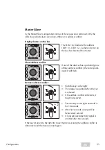
Страница 40: ...de Switch on configuration mode gn gn gn gn ge gn g gn n gn g g gn 2 Push the key to the left The audible signal will stop The 4 green LEDs flash in pairs in a diagonal sequence The lower yellow LED will light up gn gn gn gn 5 s 3 Press and hold the key to the left Three green LEDs light up The lower right hand green LED flashes 5 s ge ge ge ge The display will change after five seconds The four y...

Страница 41: ...ther submenus Advancing through menu items 1 Push the key to the left The following menu item has been selected The LED display changes A short audible signal acknowledges the key has been turned A long audible signal acknowledges each time an input is accepted Defining settings in the menu 1 Push the key to the right The LED display changes A short audible signal acknowledges the key has been tur...

Страница 42: ...uration of the guidance signal Activation delay Procedure 1 Turn the key to the right and hold it hold the key for the desired amount of time During that time the four green LEDs run clockwise one cycle each lasting one second An audible signal sounds for each second 2 Once the desired time has been reached turn the key to the left to save the time An audible signal sounds ...

Страница 43: ...porary release time 3 Door monitoring time 4 Pre alarm time 5 Alarm time 6 Guidance signal duration 7 Activation delay 8 Alarm tones 9 Request TSB address 10 Master Slave 11 Display TSB address 12 Re set to factory settings 13 Close configuration mode ...

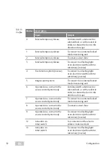
Страница 44: ...gs page 51 rt ge 6 5 4 1 2 3 9 7 8 Turn Decimal display 0 no LED 1 LED1 etc 10 LED1 9 11 LED2 9 2 Temporary release time ge Door locked af ter temporary release time interval if the door remains closed gn ge gn gn gn Hold Time freely adjustable 1 complete turn 1 second max 255 sec 3 Door moni toring time ge The time inter val starts after the door has been tempo rarily released and opened gn gn gn...

Страница 45: ...ld Time freely adjustable 1 complete turn 1 second max 255 Sec 6 Guidance signal duration ge ge After the time has elapsed the guidance signal is switched off gn ge ge gn gn gn Hold Time freely adjustable 1 complete turn 1 second max 9999 Sec 7 Activation delay ge ge When the key switch is pressed to the left The door only unlocks when the key is held for the duration of the adjusted time With the...

Страница 46: ...e next free address 1385 The device then auto matically changes to the next but one menu item Display TSB address The address 1 is automatical ly displayed in the case of the 1384 The address is requested A long audible signal is emitted when the address is identified 10 Master Slave ge rt Display of current setting address conflicts 1385 Mas ter Slave page 53 Only the mas ter is displayed in the ...

Страница 47: ...ase read the Display TSB address description section 12 Re set to factory settings ge ge ge ge The device has been re set to factory settings The yellow LEDs flash alternately in pairs ge ge ge ge gn gn gn gn 5 s 1 Hold key in position for 5 sec A long audible signal follows 13 Close configuration mode ge ge ge ge The yellow LEDs flash Tab 11 Menu items ...

Страница 48: ...up with the values 1 2 8 Adding up results in the TSB address 11 Change the TSB address At escape door appointment 1385 the connection to a connected TSB controller must be disconnected The participant address can be set manually using the key switch The adjustment of the TSB address takes place in 6 steps 1 Determine the desired LED pattern of the TSB address 2 Switch on the configuration mode 3 ...

Страница 49: ...on configuration mode 2 Switch to configuration mode Configuration page 40 Step 3 Switch on Menu 9 Change TSB address ge rt 1 Press 9 times to the left The top yellow LED illuminates the top right red LED blinks 5 s 2 Press the key to the right and hold it for five seconds Four audible signals sound The green LEDs illuminate in succession The display will change after five seconds LEDs 1 to 64 imm...

Страница 50: ... press immediately if the corre sponding LED lights up Deselect address value press immediately if the corre sponding LED goes out The address 11 is set in this example The LED pattern is 1 2 8 3 1 Example press to the right if LED 1 lights up LED 2 lights up LED 4 goes out LED 8 lights up LED 16 goes out LED 32 goes out LED 64 goes out Step 5 Save LED pattern address When the LED pattern matches ...

Страница 51: ...ds Parameters Factory setting Adjustable from to Temporary release 5 1 255 Hold open function 50 1 3600 Monitoring 60 1 3600 Pre alarm 10 1 3600 Alarm signal 180 0 255 Guidance signal 600 0 9999 Activation delay 0 0 255 Configuration using FT Manager 1385 networked If changes are made you must always select Profile 0 in FT Manager as it is the only place where changes can be saved Note Profile 0 i...

Страница 52: ...m To connect to an external locked mode monitoring unit 6 Operated via a contact in the access control system only Combined with a motorized or solenoid lock or with an electric strike to release the door in the direction of escape 7 Operated via a contact in the access control system only To connect to an external locked mode monitoring unit 8 Operated via a contact in the access control system o...

Страница 53: ...vices has a problem gone offline address conflict the correspond ing LED will flash Remove address conflict 6 5 4 1 2 3 7 8 ge rt 1 Push the key to the right The display is updated when the key is released If the address conflict still exists it must be resolved 6 5 4 1 2 3 7 8 ge rt 10 s 10 s 1 Turn the key to the right and hold it for 10 seconds After five seconds a beep will be heard every seco...

Страница 54: ...nfiguration Short circuit Short circuit is displayed 6 5 4 1 2 3 7 8 ge rt If all eight LEDs 1 8 are flashing there is a short circuit in the bus The system is not ready for operation 1 Remove the short circuit ...

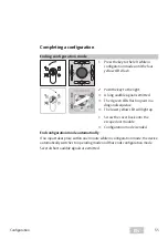
Страница 55: ...long audible signal is emitted The 4 green LEDs flash in pairs in a diagonal sequence The lower yellow LED will light up 1 Screw the cover back onto the escape door module Configuration mode is ended End configuration mode automatically If no input takes place within one minute while in configuration mode the device automatically switches to operating mode and thus ends configuration mode Several ...

Страница 56: ...on menu This is displayed by the left hand yellow LED lighting up Configuring pre alarm time 1 Now turn the key to the right and hold it for the duration of the desired pre alarm time 20 seconds The green LEDs blink alternately in clockwise motion with each cycle corresponding to one second The change you have made will be saved as soon as you let go of the key Leaving the configuration menu 1 Pre...

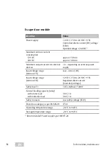
Страница 57: ...parate line Type JY St Y Cable cross section Min 0 28 mm Ideal 0 5 mm Only use one wire in each line Do not connect wires in parallel Connectible locking elements The connection of locking elements is listed in documentation D00470xx The number depends on the specified rated current consumption for external consumers Permissible device combinations in accordance with EltVTR DIN EN 13637 can be fou...

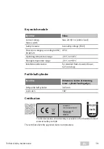
Страница 58: ...pending on external power supply Input voltage range terminal 13 Low Active 0V Input voltage range terminal 10 12 V DC 15 to 24 V DC 15 Regulated direct current low safety voltage Safety fuse F1 1 AF Littelfuse 154001 Contact loading capacity relay with ohmic load with inductive load 30V 1A 30V 1A Safety measure Low safety voltage SELV Protection category as per EN 60529 IP 30 Operating temperatur...

Страница 59: ...Installation dimensions For standard flush mounted boxes 62 5 mm deep Profile half cylinder Identifier Dimension Centre of mounting screw cylinder leading edge DIN profile half cylinder 30 5 mm Lock catch 180 Certification Sicherheitstechnik GmbH Werk Albstadt EltVTR C M ASSA ABLOY Sicherheitstechnik GmbH Bildstockstraße 20 72458 Albstadt GERMANY The EU declaration of conformity is available in th...

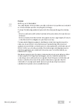
Страница 60: ...applicable environmental protection regulations must be observed Do not dispose of lamps disposable and rechargeable batteries electrical devices or personal data in the household waste Lamps and used disposable and rechargeable batteries must be removed from the device without damaging them and then disposed of separately Packaging Packaging materials must be recycled You can also give packaging ...

Страница 61: ...es with a sales area of over 400 m or to distributors of foodstuffs that offer electrical appliances several times a calendar year or continuously with a total sales area of 800 m In the case of online providers the total storage and shipping areas for electrical appliances are considered to be sales areas For further details see ElektroG3 17 1 2 Distributors using means of remote communication mu...

Страница 62: ...62 EN ...

Страница 63: ...63 EN ...

Страница 64: ... sicherer und geborgener zu fühlen und eine offenere Welt zu erleben Die ASSA ABLOY Gruppe ist der Weltmarktführer in Zugangslösungen Jeden Tag helfen wir Menschen sich sicherer und geborgener zu fühlen und eine offenere Welt zu erleben ASSA ABLOY Sicherheitstechnik GmbH Bildstockstraße 20 72458 Albstadt GERMANY Tel 49 7431 123 0 Fax 49 7431 123 240 albstadt assaabloy com www assaabloy com de Tech...

Отзывы: