


Motor Replacement
332763A
31
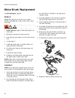
Motor Replacement
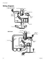
See
Wiring Diagram
, page 32.
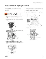
Removal
1.
Relieve pressure
, page 9. Disconnect power cord
from outlet.
2.
Remove pump (9),
Displacement Pump
Replacement
, page 17.
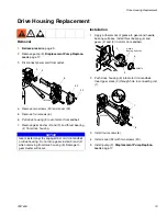
3.
Remove drive housing (5),
Drive Housing
Replacement
, page 19.
4.
Remove pressure (fluid) manifold (15),
Manifold
Replacement
, page 27.
5.
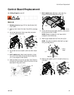
Disconnect all leads from board (33) and remove
control board. See
Control Board Replacement
,
page 23.
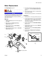
6.
Remove green ground screw (31) and ground wire
(G) from motor endbell.
7.
Remove four screws (6) and motor (1) from frame (45).
Installation
1.
Install new motor on frame (45) with four screws (6).
2.
Connect green ground wire (G) to frame with green
ground screw (31). Be sure green ground wire ter-
minal faces up or wires could get caught in shroud.
(See illustration, page 25.)
3.
Install control board (33),
Control Board Replace-
ment
, page 23.
4.
Install manifold (15) with two screws (6),
Manifold
Replacement
, page 27.
5.
Install drive housing (5).
Drive Housing Replace-
ment
, page 19.
6.
Install pump (9).
Displacement Pump Replace-
ment
, page 17.
NOTICE
Gear cluster may stay engaged in motor front endbell
or drive housing. Do not drop gear cluster (3) and (2)
when removing from drive housing (5). Damage to
gear cluster will occur.
31
33
30
6
1
3
2
6
45
34
1
1
Liberally apply grease
1
ti5642b
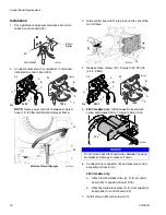
Screw
Capacitor Board
Bracket
ti22268a
230V Models Only
33a
Содержание 24U099
Страница 33: ...Notes 332763A 33 Notes ...
Страница 39: ...Notes 332763A 39 Notes ...