


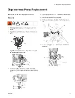


Pressure Control Assembly Replacement
26
332763A
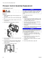
Pressure Control Assembly Replacement
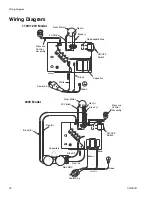
See
Wiring Diagram
, page 32.
Removal
1.
Relieve pressure
, page 9. Disconnect power cord
from outlet.
2.
Remove two screws (30) and shroud (29). See page
21.
3.
Disconnect pressure switch connector (A) from con-
trol board (33).
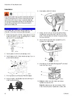
4.
Remove tape (22) holding wires to manifold.
5.
Pull bushing (21) from hole (K), then pull wires back
through hole (K).
6.
Turn pressure control knob (16) counter clockwise
as far as you can to access flats on either side of
pressure control.
7.
Loosen and unscrew pressure control.
8.
Remove pressure control.
Installation
1.
Inspect pressure control before installation to verify
o-ring is installed and in place. Verify that the wires
are routed through bushing (21).
2.
Align pressure control wire cap (17) on fluid mani-
fold so opening faces toward motor.
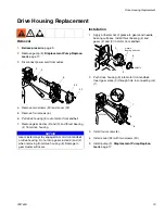
3.
Apply thread sealant to pressure control assembly
(16) threads.
4.
Screw pressure control assembly (16) into manifold
(15) and torque to 150 in-lb (17.0 N•m).
5.
Guide wires around bottom of knob and route
through slot in wire cap (17). Feed wires through
housing hole (K).
6.
Insert bushing (21) in hole (K). Use tape (22) to
secure wires to manifold housing.
7.
Connect pressure switch connector (A) to control
board (33).
8.
Install shroud (29) and two screws (30).
16
17
21
22
A
K
ti5768d
15
16
ti9128a
NOTICE
If you plan to reuse the pressure control assembly, be
very careful not to damage or tangle the wires while
unscrewing the assembly. Damage to wires may
occur.
NOTICE
Be careful when tightening pressure control knob that
wires do not get pinched between the pressure con-
trol assembly and fluid manifold.
Содержание 24U099
Страница 33: ...Notes 332763A 33 Notes ...
Страница 39: ...Notes 332763A 39 Notes ...