


51
Ubiquity Router family - User’s guide
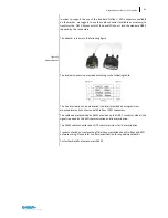
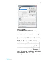
Select TCP in the upper left list.
Write the IP address of the Router (WAN or LAN port IP)
Choose where to download the project into the Router specifying the “Upload
Device Path”.
Note: the project must be transferred to the “MMCMemory” data storage de-
vice.
To transfer the project click on the button “Upload Project!”.
Once the transfer is completed, click “Start Device Project” to run the applica-
tion.
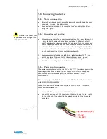
Note
: the name of the memory are according to the following table:
Memory
Name used by oper-
ating system
Note
NAND
NANDFlash
Internal memory used to
store the operating sys-
tem. It is a read only
memory.
MMC
MMCMemory
Memory to store data and
executables.
Read and Write memory.
Please refer to “Ubiquity software user guide” for additional information about
how retrieving data loggers from the RM router systems.
Note
: Ubiquity RM models with integrated 2G/3G/3G+ modem support the SMS
alarm notification; the Premium HMI Alarm Dispatcher software is already con
Содержание Ubiquity RK10
Страница 5: ...v ...
Страница 6: ......
Страница 7: ...1 Ubiquity Router family User s guide SECTION 1 1 Preliminary Information ...
Страница 13: ...7 Ubiquity Router family User s guide SECTION 2 2 Description ...
Страница 33: ...27 Ubiquity Router family User s guide SECTION 3 3 Installation and connection ...
Страница 54: ...48 SECTION 3 Installation and connection ...
Страница 55: ...49 Ubiquity Router family User s guide SECTION 4 4 Commissioning ...
Страница 59: ...53 Ubiquity Router family User s guide SECTION 5 5 Maintenance and care ...
Страница 65: ...59 Ubiquity Router family User s guide SECTION 6 6 Technical specifications ...
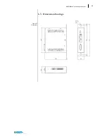
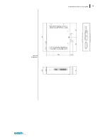
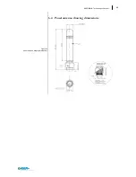
Страница 70: ...64 SECTION 8 Technical specifications Figure 57 Dimensions 6 3 Dimension drawings ...
Страница 71: ...65 Ubiquity Router family User s guide Figure 58 Dimensions ...
Страница 76: ...70 SECTION 8 Technical specifications Table 12 DC Input 6 7 3 DC Input PIN Signal 1 Vin 2 Vin 3 EARTH ...


