


41
Ubiquity Router family - User’s guide
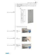
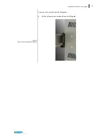
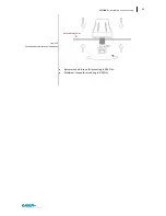
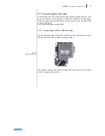
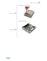
Attention: the system must
be powered with a voltage of 12V
or 24V (9V÷36V) DC.
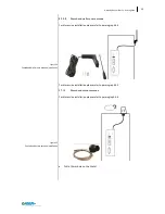
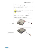
Figure 37
Power supply connection detail
3.8
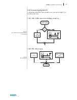
Connecting the device
3.8.1
Notes on connection
Ubiquity Router device must be installed in accordance with the indications
contained in this operating instructions.
These devices are intended to be connected to a “Secondary Circuit Over-
voltage Category II”
3.8.2
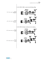
Grounding and bonding
Whenever two pieces of equipment connected to each other are far apart, it
is possible that their ground connections could be at a different potential
level. The data cable screens connecting the equipment’s chassis on one end
and the Ubiquity Router device’s chassis on the other end can therefore be
subject to a high current circulation capable of destroying the interface. To
overcome this hazard such current must be steered away from the interface.
To achieve this goal the following methods can be used:
1.
Use an equipotential bonding cable (16mm
2
, suitable at least 75C°) to con-
nect the equipment’s’ ground to the Ubiquity Router device’s ground.
2.
Connect the data cable screens to the equipotential bonding rail on both
sides before connecting the cable to the interfaces.
3.8.3
Power supply connection
The device may only be connected to a 12V or 24V
(maximum permissible
operating voltage range 9V to 36V) power supply which satisfies the require-
ments of safe extra low voltage (SELV) in accordance with IEC/EN/DIN
EN/UL60950-1.
The power supply has to fulfill the requirements NEC Class2 or LPS in accordance
with IEC/EN/DIN EN/UL60950-1
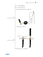
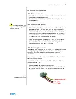
Connect the device with a cable cross-section of 0.75 – 1.5 mm
2
(AWG18 to
AWG16 suitable at least 75C°).
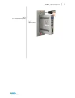
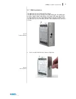
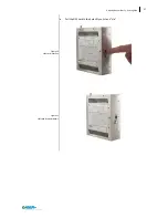
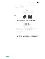
Remove the three poles connector from the system.
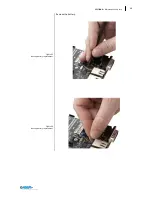
Connect the positive pole, the negative and the ground one (also refer to the
label on the back of the system) to the related terminals of the three pole
connector.
+ (24V)
EMC Ground (0V)
- (0V)
Содержание Ubiquity RK10
Страница 5: ...v ...
Страница 6: ......
Страница 7: ...1 Ubiquity Router family User s guide SECTION 1 1 Preliminary Information ...
Страница 13: ...7 Ubiquity Router family User s guide SECTION 2 2 Description ...
Страница 33: ...27 Ubiquity Router family User s guide SECTION 3 3 Installation and connection ...
Страница 54: ...48 SECTION 3 Installation and connection ...
Страница 55: ...49 Ubiquity Router family User s guide SECTION 4 4 Commissioning ...
Страница 59: ...53 Ubiquity Router family User s guide SECTION 5 5 Maintenance and care ...
Страница 65: ...59 Ubiquity Router family User s guide SECTION 6 6 Technical specifications ...
Страница 70: ...64 SECTION 8 Technical specifications Figure 57 Dimensions 6 3 Dimension drawings ...
Страница 71: ...65 Ubiquity Router family User s guide Figure 58 Dimensions ...
Страница 76: ...70 SECTION 8 Technical specifications Table 12 DC Input 6 7 3 DC Input PIN Signal 1 Vin 2 Vin 3 EARTH ...


