


19
Ubiquity Router family - User’s guide
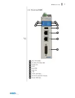
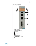
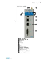
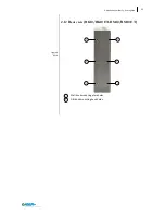
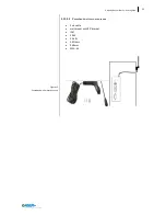
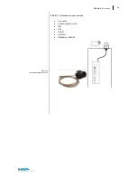
Figure 5
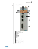
RK10
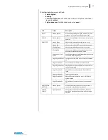
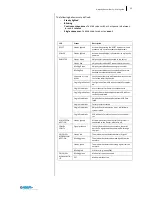
IN0
This input works as “Connection mode”, also referred as “selector key” in-
put.
By default the status of this input is ignored. When the Ubiquity Router
device is configured to handle the input (see “General options” in the
Ubiquity Router device configuration chapter) it can be used to control
from outside the connection to the server. The input can be driven by a
mechanical selector, by a key selector or by a PLC outputs.
IN1
This input allows controlling the device restart from outside. The operation
corresponds to the RESET button. Once the command is received a proper
feedback is returned by the status LED.
OUT0
The output turns active when Ubiquity Router device is connected to the
associated Domain. Note that the simple connection to the server does not
activate the output, it is required that Ubiquity is successfully authenticat-
ed to the Domain.
OUT1
The output is active when at least one Control Center client is connected
to the Ubiquity Router device.
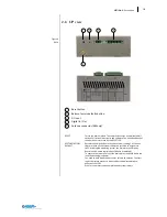
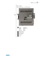
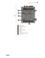
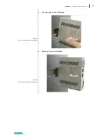
2.9
Right view
Full stainless steel enclosure
Aeration holes
2
1
1
2
2
Содержание Ubiquity RK10
Страница 5: ...v ...
Страница 6: ......
Страница 7: ...1 Ubiquity Router family User s guide SECTION 1 1 Preliminary Information ...
Страница 13: ...7 Ubiquity Router family User s guide SECTION 2 2 Description ...
Страница 33: ...27 Ubiquity Router family User s guide SECTION 3 3 Installation and connection ...
Страница 54: ...48 SECTION 3 Installation and connection ...
Страница 55: ...49 Ubiquity Router family User s guide SECTION 4 4 Commissioning ...
Страница 59: ...53 Ubiquity Router family User s guide SECTION 5 5 Maintenance and care ...
Страница 65: ...59 Ubiquity Router family User s guide SECTION 6 6 Technical specifications ...
Страница 70: ...64 SECTION 8 Technical specifications Figure 57 Dimensions 6 3 Dimension drawings ...
Страница 71: ...65 Ubiquity Router family User s guide Figure 58 Dimensions ...
Страница 76: ...70 SECTION 8 Technical specifications Table 12 DC Input 6 7 3 DC Input PIN Signal 1 Vin 2 Vin 3 EARTH ...


