


Ascon Tecnologic - KX Line - ENGINEERING MANUAL -Vr.4.0
PAG. 8
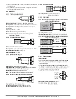
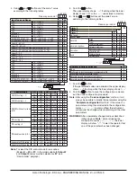
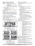
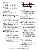
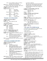
S
TC S
r
TC R
t
TC T
ir.J
Exergen IRS J
ir.cA
Exergen IRS K
Ptc PTC
ntc NTC
0.60
0... 60 mV linear
12.60
12... 60 mV linear
0.20
0... 20 mA linear
4.20
4... 20 mA linear
0.5
0... 5 V linear
1.5
1... 5 V linear
0.10
0... 10 V linear
2.10
2... 10 V linear
Notes: 1.
When a TC input is selected and a decimal figure
is programmed (see the next parameter) the max.
displayed value becomes 999.9°C or 999.9°F.
2.
Every change of the SEnS parameter setting
will force the [2] dP = 0 and it will change all
parameters related with dP (e.g. set points,
proportional band, etc.).
[2] dP - Decimal point position
Available:
Always.
Range:
When [1] SenS = Linear input: 0... 3.
When [1] SenS different from linear input: 0 or 1.
Note:
Every change of the dP parameter setting will produce
a change of the parameters related with it (e.g.: set
points, proportional band, etc.).
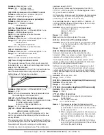
[3] SSc - Initial scale read-out for linear inputs
Available:
when a linear input is selected by [1] SenS.
Range:
-1999... 9999.
Notes: 1.
SSc allows the scaling of the analogue input to
set the minimum displayed/measured value.
The instrument will show a measured value up to
5% less then SSc value and than it will show an
underrange error.
2.
It is possible to set a initial scale read-out higher
then the full scale read-out in order to obtain a
reverse read-out scaling
E.g.:
0 mA = 0 mBar and 20 mA = -1000 mBar (vacuum).
[4] FSc - Full scale read-out for linear input
Available:
When a linear input is selected by [1] SenS.
Range:
-1999... 9999
Notes: 1.
Fsc allows the scaling of the analogue input to set
the maximum displayed/measured value.
The instrument will show a measured value up to
5% higher than [4] FSc value and then it will show
an overrange error.
2.
It is possible to set a full scale read-out lower
than the initial scale read-out in order to obtain a
reverse read-out scaling.
E.g.:
0 mA = 0 mBar and 20 mA = -1000 mBar (vacuum).
[5] unit - Engineering unit
Available:
When a temperature sensor is selected by [1]
SenS parameter.
Range:
°c = Centigrade
°F = Fahrenheit
[6] FiL - Digital filter on the measured value
Available:
Always
Range:
oFF (No filter) 0.1 to 20.0 s
Note:
This is a first order digital filter applied on the
measured value. For this reason it will affect the
measured value but also the control action and the
alarms behaviour.
[7] inE - Selection of the Sensor Out of Range type
that will enable the safety output value
Available:
Always
Range: our
=
When an overrange or an underrange is
detected, the power output will be forced to
the value of [8] oPE parameter.
or
=
When an overrange is detected, the power
output will be forced to the value of [8] oPE
parameter.
ur
=
When an underrange is detected, the po-
wer output will be forced to the value of [8]
oPE parameter.
[8] oPE - Safety output value
Available:
Always
Range:
-100... 100 % (of the output).
Notes: 1.
When the instrument is programmed with one
control action only (heat or cool), setting a
value outside of the available output range, the
instrument will use Zero.
E.g.
: When heat action only has been
programmed, and oPE is equal to -50% (cooling)
the instrument will use the zero value.
2.
When ON/OFF control is programmed and an out
of range is detected, the instrument will perform
the safety output value using a fixed cycle time
equal to 20 seconds.
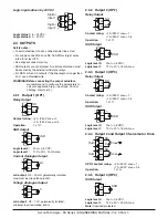
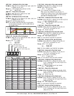
[9] io4.F - I/O4 function selection
Available:
Always
Range: on
=
The out 4 will be always ON (used as a
transmitter power supply);
out4
= used as digital output 4;
dG2.c
= Digital input 2 for contact closure;
dG2.u
= Digital input 2 driven by 12... 24 VDC.
Notes: 1.
Setting [9] io4.F = dG2.C o dG2V, the [24] O4F
parameter becomes not visible while [11] diF2
parameter will become visible.
2.
Setting [9] io4F = on the [24] O4F parameter and
the [11]diF2 parameter will NOT be visible.
3.
Setting [9] io4F different from dG2.c or dG2.U,
the instrument will force [12] diF2 parameter
equal to nonE
If [11] diF1 was equal to (SP4 or UPDN) it will be
forced to nonE.
4.
The transfer from [9] io4F = on to [9] io4F = Out
4 will make the [24] O4F parameter visible equal
to nonE.
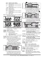
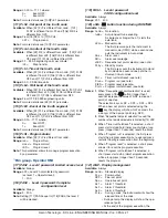
[10] diF1 - Digital input 1 function
Available:
Always.
Range: oFF
= No function
1
Alarm Reset [status]
2
Alarm acknowledge (ACK) [status].
3
Hold of the measured value [status].
4
Stand by mode of the instrument [status]