background image

Ascon Tecnologic - KX Line - ENGINEERING MANUAL -Vr.4.0

 PAG. 30

Appendix A


]

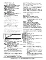
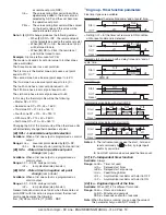
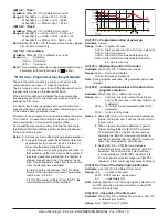
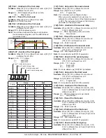
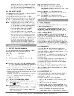
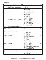
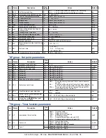
inP GROuP - Main and auxiliary input configuration

no. Param.

Description

Dec. 

Point

Values

Default

1

SEnS

Sensor selection (according to the HW)

Model C

0

J = TC J,

crAL = TC K,

S = TC S,

r = TC R,

t = TC T,

ir.J = IRS J,

ir.cA = IRS K, 

Pt1 = RTD Pt100,

Pt10 = RTD Pt1000,

0.60 = 0... 60 mV,

12.60 = 12... 60 mV,

0.20 = 0... 20 mA,

4.20 = 4... 20 mA,

0.5 = 0... 5 V,

1.5 = 1... 5 V, 

0.10 = 0... 10 V,

2.10 = 2... 10 V

J

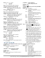
Model E

J = TC J,

crAL = TC K,

S = TC S,

r = TC R,

t = TC T,

ir.J = IRS J,

ir.cA = IRS K,

Ptc = TC KTY81-121,

ntc = NTC 103-AT2,

0.60 = 0... 60 mV,

12.60 = 12... 60 mV,

0.20 = 0... 20 mA,

4.20 = 4... 20 mA,

0.5 = 0... 5 V,

1.5 = 1... 5 V, 

0.10 = 0... 10 V,

2.10 = 2... 10 V

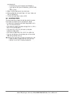
2

dp

Decimal Point Position (linear inputs)

0

0... 3

0

Decimal Point Position (different than linear inputs)

0/1

3

SSC

Initial scale read-out for linear inputs

dp

-1999... 9999

0

4

FSc

Full Scale Readout for linear inputs

dp

-1999... 9999

1000

5

unit

Engineer unit

°C/°F

°C

6

Fil

Digital filter on the measured value

1

0 (= OFF)... 20.0 s

1.0

7

inE

Sensor error used to enable the safety output 

value

or = Over range

ou = Under range

our = Over and under range

our

8

oPE

Safety output value (% of the output)

-100...  100

0

9

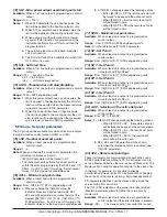
IO4.F

I/O 4 function

on = 

Output used as PWS for TX,

out4 =  Output 4 (digital output 4),

dG2c =  Digital input 2 driven by contact,

dG2U =  Digital input 2 driven by voltage

out4

Содержание KX Series

Страница 1: ...pen Close KX3 only 1 2 3 4 5 6 7 8 9 10 11 12 13 14 15 16 2 1 Mounting requirements This instrument is intended for permanent installation for indoor use only in an electrical panel which encloses the rear housing exposed terminals and wiring on the back Select a mounting location having the following characteristics 1 It should be easily accessible 2 There is minimum vibrations and no impact 3 Th...

Страница 2: ...tance of the 3 wires must be the same 2 3 4 RTD Pt 1000 NTC and PTC Input 2 3 Pt1000 Line resistance Not compensated Pt 1000 input circuit Current injection 15 µA Pt 1000 calibration According to EN 60751 A2 2 3 5 V and mV Input mV V _ _ 1 2 Input impedance 1 MΩ for mV Input 500 kΩ for Volt Input 2 3 6 mA Input 0 4 20 mA input wiring for passive transmitter using the auxiliary pws _ 4 20 mA Passiv...

Страница 3: ...0 V cosj 0 4 Operation 1 x 10⁵ SSR Output SSR 9 10 Logic level 0 Vout 0 5 VDC Logic level 1 12 V 20 15 mA max Current Analogue Output mA 9 10 mA output 0 4 20 mA galvanically isolated maximum load resistance 600Ω Voltage Analogue Output V 9 10 mA output 0 2 10 V galvanically isolated minimum load resistance 500Ω 2 4 2 Output 2 OP2 Relay Output C NO 11 12 Contact rating 2 A 250 V cosj 1 1 A 250 V c...

Страница 4: ... Panel cutout 45 0 6 x 89 0 6 mm 1 78 0 023 x 3 5 0 023 in Weight 160 g max Power supply 24 VAC DC 10 of the nominal value 100 240 VAC 15 10 of the nominal value Power consumption 5 VA max Insulation voltage 2300 V rms according to EN 61010 1 Display updating time 500 ms Sampling time 130 ms Resolution 30000 counts Total Accuracy 0 5 F S V 1 digit 25 C of room temperature Electromagnetic compatibi...

Страница 5: ...onfiguration modes Note The KX Line is equipped with two different configuration methods A The code configuration method B The complete configuration method The code configuration method is really fast but modifies only the most common configuration parameters The complete configuration method allows to take advantage of all instrument features giving more capabilities it requires more actions and...

Страница 6: ...te To select the PID control mode for servodrive N plus O 20 or 21 in the order code both Output 2 and Output 3 codes must be selected as M see How to order pargraph 5 Push the button The upper display shows cod2 flashing while the lower display shows 0000 or the cod2 value stored in memory 6 Using and buttons set the code 2 value according to the following tables P Q R S Prepare your code 2 Alarm...

Страница 7: ...ase the value of the selected parameter These two keys allow to return to the previous group Proceed as follows Push the button and maintaining the pressure then push the button release both the buttons Note The group selection is cyclic as well as the selection of the parameters in a group 4 5 Factory reset default parameters loading procedure Sometime e g when you re configure an instrument prev...

Страница 8: ... Centigrade F Fahrenheit 6 FiL Digital filter on the measured value Available Always Range oFF No filter 0 1 to 20 0 s Note This is a first order digital filter applied on the measured value For this reason it will affect the measured value but also the control action and the alarms behaviour 7 inE Selection of the Sensor Out of Range type that will enable the safety output value Available Always ...

Страница 9: ...ansition Short closure allows to start timer execution and to suspend it while a long closure longer than 10 seconds allows to reset the timer 8 Timer Run transition a short closure allows to start timer execution 9 Timer reset transition a short closure allows to reset timer count 10 Timer run hold Status Contact closure timer RUN Contact opend timer Hold 11 Timer run reset status 12 Timer run re...

Страница 10: ...99 to 15 Ao1H 15 A o1H Full scale value of the analogue retransmission KX3 only Available When Out 1 is a linear output and 13 O1F is equal to r IMP r Err r SP or r SEr Range 14 Ao1L to 9999 16 o1 AL Alarms linked up with the out 1 Available When 13 o1F AL Range 0 63 with the following rules 1 Alarm 1 2 Alarm 2 4 Alarm 3 8 Loop break alarm 16 Sensor break burn out 32 Overload on Out 4 short circui...

Страница 11: ... 4 Alarm 3 8 Loop break alarm 16 Sensor break burn out 32 overload on Out 4 short circuit on OP 4 For more details see 16 o1 AL parameter 23 o3Ac Out 3 action Available when 20 o3F is different from nonE Range dir Direct action rEU Reverse action dir r Direct action with revers LED indication rEU r Reverse action with reverse LED indication For more details see 17 o1 Ac parameter 24 o4F Out 4 func...

Страница 12: ...n alarm that will remain active even if the conditions that generated the alarm no longer persist Alarm reset can be done only by an external command button digital inputs or serial link Alarm reset Alarm reset AL1 PV time off off Ab1 2 Ab1 0 off off ON ON 3 An Acknowledgeable alarm is an alarm that can be reset even if the conditions that generated the alarm are still present Alarm acknowledge ca...

Страница 13: ...ed as control output nonE Alarm not used LoAb Absolute low alarm HiAb Absolute high alarm LHAo Absolute band alarm with alarm indication out of the band LHAi Absolute band alarm with alarm indication inside the band SE br Sensor break Note The relative alarm are relative to the current set point this may be different from the Target setpoint if you are using the ramp to set point function 36 Ab2 A...

Страница 14: ...48 HAL3 Alarm 3 hysteresis Available When 43 AL3t is different to nonE or 43 AL3t is different from SE br Range 1 9999 engineering units Note For other details see 32 HAL1 parameter 49 AL3d Alarm 3 delay Available When 43 AL3t different form nonE Range From oFF 0 to 9999 seconds Note The alarm goes ON only when the alarm condition persist for a time longer than 49 AL3d time but the reset is immedi...

Страница 15: ...lection Ascon Tecnologic has developed three auto tune algorithms Oscillating auto tune Fast auto tune EvoTune 1 The oscillating auto tune is the usual auto tune and It is more accurate Can start even if PV is close to the set point Can be used even if the set point is close to the ambient temperature 2 The fast type is suitable when The process is very slow and you want to be opera tive in a shor...

Страница 16: ...l to 250 C When you want to increase the temperature from 250 to 270 C DT 20 C using 100 of the heating power resis tor you will need 60 seconds On the contrary when you want to decrease the temperature from 250 to 230 C DT 20 C using 100 of the cooling power fan you will need 20 seconds only In our example the ratio is equal to 60 20 3 66 rcG 3 and it say that the efficiency of the cooling system...

Страница 17: ...6 Pr S3 111 Pr S4 parameters If an SP is out of this range the instrument forces it to the maximum acceptable value 2 A 76 SPLL change produces the following actions When 83 SP rt SP the remote set point will be forced to be equal to the active set point When 83 SP rt trim the remote set point will be forced to zero When 83 SP rt PErc the remote set point will be forced to zero 77 SPHL Maximum set...

Страница 18: ...mp up Available When at list one output is e programmed as control output Range 0 01 99 99 units per minute inF ramp disabled step transfer 86 SP d Rate of rise for negative set point change ramp down Available When at list one output is e programmed as control output Range 0 01 99 99 units per minute inF ramp disabled step transfer General note about remote set point when the remote set point RSP...

Страница 19: ...ures the 127 dSPu Status of the instrument at power u parameter must be set to AS Pr If 127 dSPu value is different from AS Pr the memorization function will be inhibited PWR UP or RUN Time Spx Status Temperature OFF 2 p m a R Soak 2 3 p m a R Soak 3 4 k a o S 4 p m a R Ramp to Spx Prog END Prog Step Pr S1 1 p m a R 1 k a o S Program run Pr S4 Pr S2 Pr S3 92 Pr F Programmer action at power up Avai...

Страница 20: ...oup equal to OFF The instrument will mask all the following parameters of the programmer 102 Pr G2 Gradient of the second ramp Available When 92 Pr F is different from nonE and 102 Pr S2 is different from oFF Range 0 1 999 9 engineering units per minute inF Step transfer 103 Pr t2 Time of the second soak Available When 92 Pr F is different from nonE and 101 Pr S2 is different from oFF Range 0 00 9...

Страница 21: ...o 118 PAS3 the level 2 will be masked 119 PAS4 Level 4 password CODE configuration level Available Always Range 201 400 120 uSrb button function during RUN TIME Available Always Range nonE No function tunE Auto tune self tune enabling A single press longer than 1 starts the auto tune oPLo Manual mode The first pressure puts the instrument in manual mode OPLO while a second one puts the instrument ...

Страница 22: ...er to show that the instrument is working correctly If an alarm occures or a buton is pressed the display will come back to the normal operation 125 FiLd Filter on the displayed value Available Always Range oFF Filter disabled From 0 0 oFF to 20 0 engineering units Note This is a window filter related to the set point it is applied to the displayed value only and it have no effect on the other fun...

Страница 23: ...e service inspection intervals It works every time the instrument is turned ON When the count reaches the programmed threshold the display shows alternately the standard display and the message r iSP requested Inspection The count reset can be done only by changing the threshold value 134 UoLt Nominal Voltage of the load Available When 133 Co tY ist or 133 Co tY h or 133 Co tY S S Range 1 9999 V 1...

Страница 24: ...gest to operate as follows 1 Prepare the exact parameter list you want to make accessible for limited access 2 Number the desired parameters in the same sequence you want to have in the limited access 3 Define which of the selected parameter will be available in Operator level also Example I would like to obtain the following limited access list OPEr Operative mode selection SP first set point SP2...

Страница 25: ... memorize the new value and go to the next parameter 5 When you want to come back to the standard display push the button for more than 5 seconds Note The parameter modification of the Operator level is subject to a time out If no button is pressed for more than 10 seconds the instrument goes back to the standard display and the new value of the last selected parameter will be lost 6 2 Enter the L...

Страница 26: ... hence in many cases only part of this information is available 1 When the instrument is showing the standard display push button The lower display will show H or c followed by a number This value is the current power output applied to the process The H show you that the action is a Heating action while the c show you that the action is a Cooling action 2 Push button again When the programmer is r...

Страница 27: ...in there until a new panel arrives 6 4 5 Display management This instrument allows you to program see parameter 124 diS t the time out of the display This function allows to turn OFF the display when no alarm is present and no action is made on the instrument When 124 diS t is different to OFF display always ON and no button is pressed for more than the programmed time out the display goes OFF and...

Страница 28: ... output restart to operate NoAt Auto tune not finished within 12 hours ErEP Possible problem of the instrument memory The messages disappears automatically When the error continues send the instrument to your supplier RonE Possible problem of the firmware memory When this error is detected send the instrument to your supplier Errt Possible problem of the calibration memory When this error is detec...

Страница 29: ...into which a special tool can be inserted This tool named A01 allows To memorize a complete instrument configuration and to use it for other instruments To transfer a complete instrument configuration to a PC or from a PC to an instrument To transfer from a PC to an instrument a complete instrument configuration To transfer a configuration from an A01 to another one To test serial interface of the...

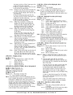
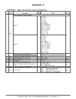
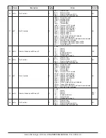
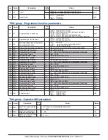
Страница 30: ...0 12 60 mV 0 20 0 20 mA 4 20 4 20 mA 0 5 0 5 V 1 5 1 5 V 0 10 0 10 V 2 10 2 10 V 2 dp Decimal Point Position linear inputs 0 0 3 0 Decimal Point Position different than linear inputs 0 1 3 SSC Initial scale read out for linear inputs dp 1999 9999 0 4 FSc Full Scale Readout for linear inputs dp 1999 9999 1000 5 unit Engineer unit C F C 6 Fil Digital filter on the measured value 1 0 OFF 20 0 s 1 0 7...

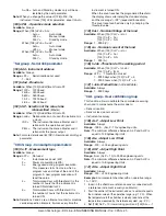
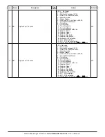
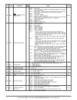
Страница 31: ...gram Run Hold 17 Program Run Reset 18 Sequential SP selection 19 SP1 SP2 selection 20 SP1 SP4 binary selection 21 Digital inputs in parallel to and keys oFF 11 diF2 Digital Input 2 function oFF Not used 1 Alarm reset 2 Alarm acknowledge ACK 3 Hold of the measured value 4 Stand by mode 5 Manual mode 6 HEAt with SP1 and CooL with SP2 7 Timer RUN Hold Reset 8 Timer Run 9 Timer Reset 10 Timer Run Hold...

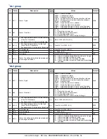
Страница 32: ... diF 2 Out1 repeats the digital input 2 status on Out1 always ON 14 Ao1L Initial scale value of the analog retransmis sion KX3 only dP 1999 Ao1H 1999 15 Ao1H Full scale value of the analog retransmission KX3 only dP Ao1L 9999 9999 16 o1AL Alarms linked up with the out 1 0 0 63 1 Alarm 1 2 Alarm 2 4 Alarm 3 8 Loop break alarm 16 Sensor Break 32 Overload on output 4 AL1 17 o1Ac Out 1 action 0 dir Di...

Страница 33: ...AL 22 o3AL Alarms linked up with the out 3 0 0 63 1 Alarm 1 2 Alarm 2 4 Alarm 3 8 Loop break alarm 16 Sensor Break 32 Overload on output 4 AL2 23 o3Ac Out 3 action 0 dir Direct action rEU Reverse action dir r Direct with reversed LED ReU r Reverse with reversed LED dir 24 o4F Out 4 function 0 NonE Output not used H rEG Heating output c rEG Cooling output AL Alarm output t out Timer output t HoF Ti...

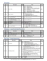
Страница 34: ...bled in stand by mode 2 Alarm 1 enabled in out of range condition 3 Alarm 1 enabled in stand by mode and in overrange condition 0 AL2 group no Param Description Dec Point Values Default 35 AL2t Alarm 2 type 0 nonE Alarm not used LoAb Absolute low alarm HiAb Absolute high alarm LHAo Windows alarm in alarm outside the windows LHAI Windows alarm in alarm inside the windows SE br Sensor Break LodE Dev...

Страница 35: ...ondition 0 LBA group Loop Break Alarm Parameters no Param Description Dec Point Values Default 51 LbAt LBA time 0 From 0 oFF to 9999 s oFF 52 LbSt Delta measure used by LBA during Soft start dP From 0 oFF to 9999 E U 10 53 LbAS Delta measure used by LBA dP 1 9999 E U 20 54 LbcA Condition for LBA enabling 0 uP Active when Pout 100 dn Active when Pout 100 both Active in both cases both rEG group Con...

Страница 36: ... 1 4 1 76 SPLL Minimum set point value dP From 1999 to SPHL 1999 77 SPHL Maximum set point value dP From SPLL to 9999 9999 78 SP Set point 1 dP From SPLL to SPLH 0 79 SP 2 Set point 2 dP From SPLL to SPLH 0 80 SP 3 Set point 3 dP From SPLL to SPLH 0 81 SP 4 Set point 4 dP From SPLL to SPLH 0 82 A SP Selection of the active set point 0 From 1 SP 1 to nSP 1 83 SP rt Remote set point type 0 RSP The v...

Страница 37: ... 100 Pr E1 Events of the 1st group 2 00 00 11 11 00 00 101 Pr S2 Set point of the 2nd soak dP OFF or from SPLL to SPHL 0 102 Pr G2 Gradient of the 2nd ramp 1 0 1 999 9 inF Step transfer Engineering Unit minute inF 103 Pr t2 Time of the 2nd soak 2 0 00 99 59 0 10 104 Pr b2 Wait band of the 2nd soak dP From 0 oFF to 9999 E U oFF 105 Pr E2 Events of the 2nd group 2 00 00 11 11 00 00 106 Pr S3 Set poi...

Страница 38: ...he instrument shows t End messages alternately with the measured value P t td When the programmer is running the display shows the total remaining time count down At the end of the program execution the instrument shows P End messages alternately with the measured value ti uP When the timer is running the display shows the timer counting up At the end of the counting the instrument shows t End mes...

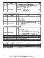
Страница 39: ...ent become a Master and it retransmits the power output nonE COn group Consumption parameters no Param Description Dec Point Values Default 133 Co tY Measurement type oFF Not used 1 Instantaneous power kW 2 Power consumption kW h 3 Energy used during program execution This measure starts from zero when a program runs end stops at the end of the program A new program execution will reset the value ...

Страница 40: ...Ascon Tecnologic KX Line ENGINEERING MANUAL Vr 4 0 PAG 40 ...

Отзывы: