


ASCON TECNOLOGIC - TLK33 - OPERATING INSTRUCTIONS -
PAG. 5
If instead, it is desired that the offset set should not be constant for
all the measurements, it is possible to operate the calibration on
any two points.
In this case, in order to decide which values to program on par.
“OFSt” and “rot”, the following formulae must be applied :
“rot” = (D2-D1) / (M2-M1)
“OFSt” = D2 - (“rot” x M2)
where:
M1 =measured value 1
D1 = visualisation value when the instrument measures M1
M2 =measured value 2
D2 = visualisation value when the instrument measures M2
It then follows that the instrument will visualise :
DV = MV x “rot” + “OFSt”
where: DV = visualised value
MV= measured value
Example 1: It is desired that the instrument visualises the value
effectively measured at 20° but that, at 200°, it visualises a value
lower than 10° (190°).
Therefore : M1=20 ; D1=20 ; M2=200 ; D2=190
“rot” = (190 - 20) / (200 - 20) = 0,944
“OFSt” = 190 - (0,944 x 200) = 1,2
Example 2: It is desired that the instrument visualises 10° whilst the
value actually measured is 0°, but, at 500° it visualises a 50° higher
value (550°).
Therefore : M1=0 ; D1=10 ; M2=500 ; D2=550
“rot” = (550 - 10) / (500 - 0) = 1,08
“OFSt” = 550 - (1,08 x 500) = 10
By using par.
“FiL”
it is possible to
program time constant of the
software filter for the input value measured, in order to reduce
noise sensitivity (increasing the time of reading).
In case of measurement error, the instrument supplies the power
as programmed on par.
“OPE”.
This power will be calculated according to cycle time programmed
for the PID controller.
By using par.
“InE”
it is also possible to decide the conditions of
the input error, allowing the instrument to give the power
programmed on par. “OPE” as output.
The possibilities of par. “InE” are :
= Or : the condition occurs in case of over-range or probe breakage
= Ur : the condition occurs in case of under-range or probe
breakage
= Our : the condition occurs in case of over-range or under-range
or probe breakage
Using par.
“diSP”,
located in the group
“
]
PAn”,
it is possible to set
normal visualization of the display which can be the process
variable (dEF), the control power (Pou), the active Set Point (SP.F)
the Set Point operating when there are active ramps (SP.o) or
alarm threshold AL1, AL2 (AL1, AL2).
Again in the group
“
]
PAn”
the par.
“AdE”
is present that defines
the 3 led shift index functioning.
The lighting up of the green led = indicates that the process value
is within the range [SP+AdE ... SP-AdE], the lighting up of the led –
indicates that the process value is lower than [SP-AdE] and the
lighting up of the led + indicates that the process value is higher
than [SP+AdE].
4.2 - DOUBLE ACTION PID CONTROL
All the parameters referring to PID control are contained in the
group
“
]
rEG”.
The Double Action PID control is used to control plants where there
is an element which causes a positive increase (ex. Heating) and
an element which causes a negative increase (ex. Cooling).
The double action PID controller is used to control plants equipped
with an actuator that causes both a positive increment (e.g.
Heating) and a negative increment (e.g. Cooling).
This is the case of temperature control using a PELTIER device
where it is possible to obtain a heating effect polarizing in one
direction and a cooling effect when polarizing in the other direction.
The Double Action PID control works on the output depending on
the active Set Point
“SP”
and on the instrument’s PID algorithm
with two degrees of freedom.
The Double Action PID control algorithm needs the programming of
the following parameters :
"Pb"
- Proportional Band
"tcr1"
- Cycle time for HEAT action
“tcr 2”
- Cycle time for COOL action
"Int"
- Integral Time
"rS"
- Manual Reset (if “Int =0 only)
"dEr"
- Derivative Time
“FuOC” -
Fuzzy Overshoot Control
"Prat"
- Power Ratio or relation between Cooling power and
Heating power
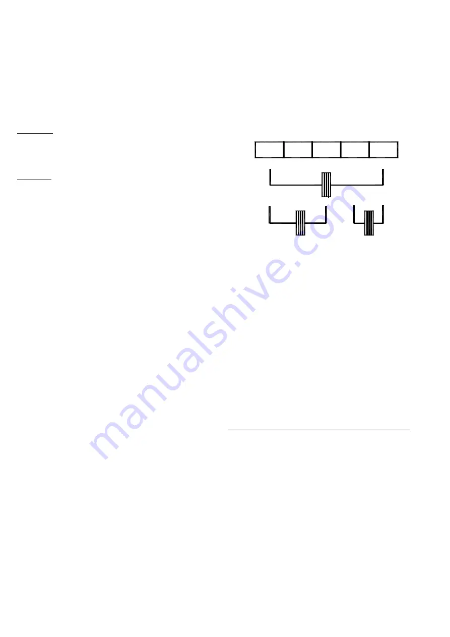
The connection of the Peltier device to the instrument indicated on
the wiring diagram always foresees a double action control, as it is
the instrument that automatically commands and polarizes the
Peltier device depending on the action to be effected (HEATING or
COOLING).
In the case that the actuator must carry out only one action, the
Peltier device can be connected to the instrument in such a way to
command only activation and not polarization.
1 8
1 6
1 7
1 5
1 4
+ H E A T
+ C O O L
( A U T O )
+
H E A T
C O O L
+
O N L Y
O N L Y
C O O L
H E A T &
4.3 - AUTOTUNING
AND SELFTUNING FUNCTIONS
All the parameters referring to the AUTO-TUNING and SELF-
TUNING functions are contained in the group
“
]
rEG”.
The AUTO-TUNING and SELF-TUNING functions permit the
automatic tuning of the PID controller.
The
AUTO-TUNING
function permits the calculation of thePID
parameters by means of a FAST type tuning cycle and, at the end
of this operation, the parameters are stored into the instrument’s
memory and remain constant during control.
The
SELF-TUNING
function (rule based "TUNE-IN") instead allows
control monitoring and the continuous calculation of the parameters
during control.
Both functions automatically calculate the following parameters :
"Pb"
- Proportional Band
"tcr1"
- Cycle time for HEAT action
“tcr 2”
- Cycle time for COOL action
"Int"
- Integral Time
"dEr"
- Derivative Time
“FuOC” -
Fuzzy Overshoot Control
"Prat"
- Power Ratio or relation between Cooling power and
Heating power
To activate the AUTO-TUNING function proceed as follows :
1) Program and activate the desired Set Point.
2) Program par.
"Auto"
as:
- "1” – if auto-tuning is desired automatically, each time the
instrument is switched on, on the condition that the process value is
lower (with “Func” =HEAt) than [SP- |SP/2|] or higher (with “Func”
=CooL) than [SP+ |SP/2|].
- "2" – if auto-tuning is desired automatically, the next time the
instrument is switched on, on the condition that the process value is
lower (with “Func” =HEAt) than [SP- |SP/2|] or higher (with “Func”
=CooL) than [SP+ |SP/2|], and once the tuning is finished, the par.
“Auto” is automatically swapped to the OFF state
- "3" - if manual auto-tuning is desired, by selecting par. “tunE” in
the main menu or by correctly programming key “U” as “USrb” =
tunE. The Autotuning will start at the condition that the process
value is lower (with “Func” =HEAt) than [SP- |SP/5|] or higher (with
“Func” =CooL) than [SP+ |SP/5|].
- "4" - if it’s desired to activate the autotuning automatically to
every change of Set Point, or at the end of programmed Soft-Start
cycle. The Autotuning will start at the condition that the process
value is lower (with “Func” =HEAt) than [SP- |SP/5|] or higher (with
“Func” =CooL) than [SP+ |SP/5|].