


ASCON TECNOLOGIC - TLK33 - OPERATING INSTRUCTIONS -
PAG. 4
remember that the plant has to be equipped with additional devices
which will guarantee safety.
3.2 – MECHANICAL MOUNTING
The instrument, in case 33 x 75 mm, is designed for flush-in panel
mounting.
Make a hole 29 x 71 mm and insert the instrument, fixing it with the
provided special bracket.
We recommend that the gasket is mounted in order to obtain the
front protection degree as declared. Avoid placing the instrument in
environments with very high humidity levels or dirt that may create
condensation or introduction of conductive substances into the
instrument.
Ensure adequate ventilation to the instrument and avoid installation
in containers that house devices which may overheat or which may
cause the instrument to function at a higher temperature than the
one permitted and declared.
Connect the instrument as far away as possible from sources of
electromagnetic disturbances such as motors, power relays, relays,
solenoid valves, etc.
3.3 - ELECTRICAL CONNECTION
Carry out the electrical wiring by connecting only one wire to each
terminal, according to the following diagram, checking that the
power supply is the same as that indicated on the instrument and
that the load current absorption is no higher than the maximum
electricity current permitted.
As the instrument is built-in equipment with permanent connection
inside housing, it is not equipped with either switches or internal
devices to protect against overload of current: the installation will
include an overload protection and a two-phase circuit-breaker,
placed as near as possible to the instrument, and located in a
position that can easily be reached by the user and marked as
instrument disconnecting device which interrupts the power supply
to the equipment.
It is also recommended that the supply of all the electrical circuits
connected to the instrument must be protect properly, using
devices (ex. fuses) proportionate to the circulating currents.
It is strongly recommended that cables with proper insulation,
according to the working voltages and temperatures, be used.
Furthermore, the input cable of the probe has to be kept separate
from line voltage wiring. If the input cable of the probe is screened,
it has to be connected to the ground with only one side.
The power supply for the instrument must be between 12 to 24
Volts DC and with enough power to pilot the instrument and Peltier
device.
The instrument has no isolation between the power supply, input
and output, therefore make sure that the probe is isolated with
respect to the power supply and outputs.
For applications that install more than one instrument, use a
different power supply for each instrument, as there is no isolation
between the power supply and input.
We recommend that a check should be made that the parameters
are those desired and that the application functions correctly before
connecting the outputs to the actuators so as to avoid
malfunctioning that may cause irregularities in the plant that could
cause damage to people, things or animals.
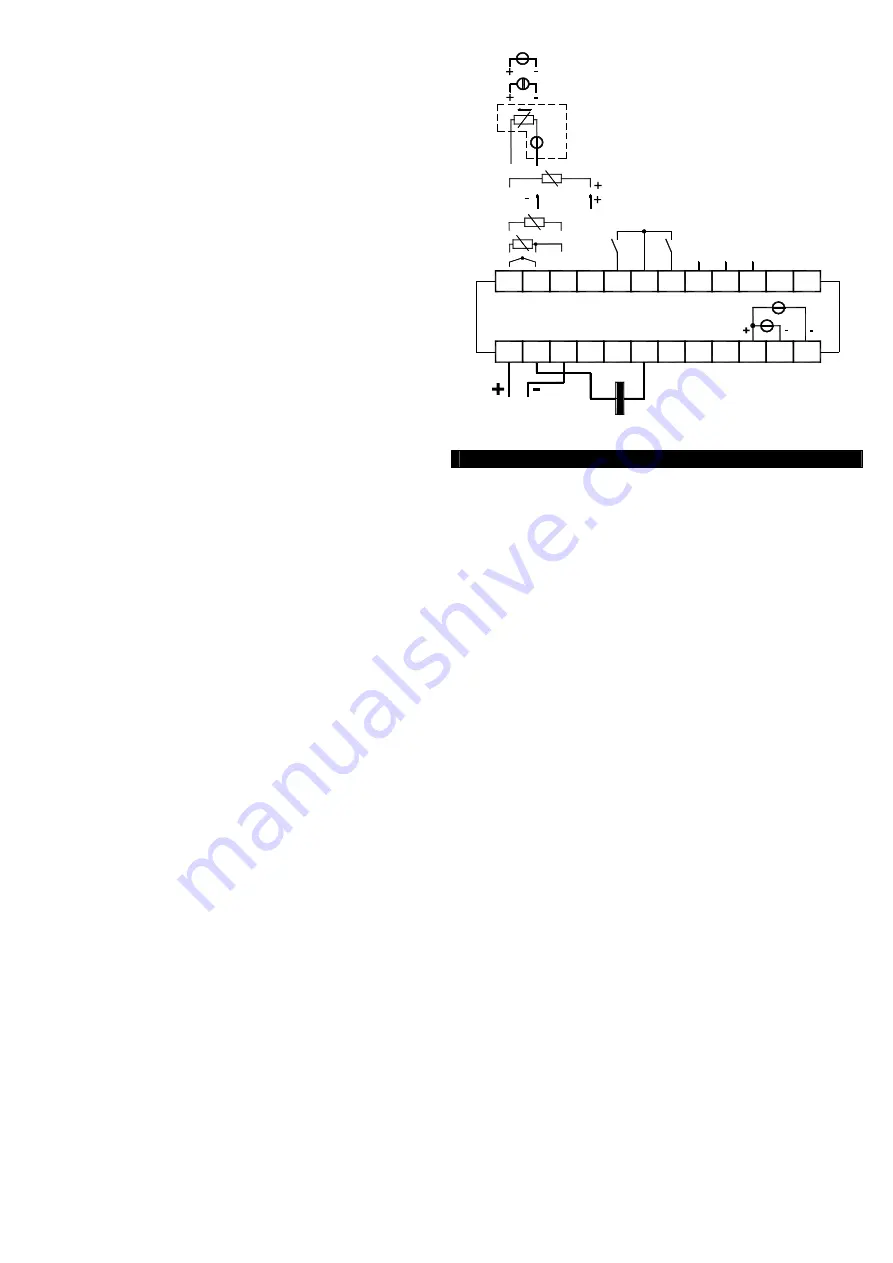
3.4 - ELECTRICAL WIRING DIAGRAM
0/1..5 V
0..50/60 mV
0/4..20 mA ACTIVE
OUT 12 VDC
Max 20 mA
3
2
1
SUPPLY
14
13
15
+
PASSIVE
4..20 mA
(2 wires)
PTC-NTC
TC/mV
Pt100
+
+
gen.
ext.
-
I
+
12
10 11
9
8
7
5
4
6
22
SSR:10mA/10VDC
17
16
18
20
19
21
AL1
23 24
A
DIG
IN2
IN1
DIG
ACTIVE
B
GND
RS 485
0...1 V
0/2..10 V
4..20 mA
12..24 VDC
+ COOL
+ HEAT
7A MAX.
PELTIER MODULE
AL2
C
TLK 33
4 - FUNCTIONS
4.1 - MEASURING AND VISUALIZATION
All the parameters referring measurements are contained in the
group
“
]
InP”.
Depending on the model required the input accept:
D
: Thermoresistances PT100, Thermocouples temperature probes
(J,K,S and ZIS Infrared sensors), mV signals (0..50/60 mV, 12..60
mV),
E
: Thermistors PTC and NTC, Thermocouples temperature probes
(J,K,S and ZIS Infrared sensors), mV signals (0..50/60 mV, 12..60
mV),.
I
: normalized analogue signals 0/4..20 mA
V
: normalized analogue signals 0..1 V, 0/1..5 V, 0/2..10 V
Depending on the model, using par.
“SEnS”,
it’s possible to select
the type of input probe, which can be :
- for thermocouples J (J), K (CrAL), S (S) or for infrared sensors
serie ZIS with linearization J (Ir.J) or K (Ir.CA)
- for thermoresistances Pt100 IEC (Pt1) or thermistors PTC KTY81-
121 (Ptc) or NTC 103AT-2 (ntc)
- for normalised signals in current 0..20 mA (0.20) or 4..20 mA
(4.20)
- for normalised signals in tension 0..1 V (0.1), 0..5 V (0.5), 1..5 V
(1.5), 0..10 V (0.10) or 2..10 V (2.10).
- for normalised signals in tension 0..50 mV (0.50), 0..60 mV (0.60),
12..60 mV (12.60).
We recommend to switch on and off the instrument when these
parameters are modified, in order to obtain a correct measuring.
For the instruments with input for temperature probes (tc, rtd) it’s
possible to select, through par.
“Unit”,
the unit of measurement
(°C, °F) and, through par.
“dP”
(Pt100, PTC and NTC only)
the
desired resolution (0=1°; 1=0,1°).
Instead, with regards to the instruments with normalised analogue
input signals, it is first necessary to program the desired resolution
on par.
“dP”
(0=1; 1=0,1; 2=0,01; 3=0,001) and then, on par.
"SSC"
, the value that the instrument must visualise at the
beginning of the scale (0/4 mA, 0/12 mV, 0/1 V o 0/2 V) and, on
par.
"FSC",
the value that the instrument must visualise at the end
of the scale (20 mA, 50 mV, 60 mV, 5 V or 10 V).
The instrument allows for measuring calibration, which may be
used to recalibrate the instrument according to application needs,
by using par.
“OFSt”
and
“rot”.
Programming par. “rot”=1,000, in par. “OFSt” it is possible to set a
positive or negative offset that is simply added to the value read by
the probe before visualisation, which remains constant for all the
measurements.