22
1222AHS OPERATORS MANUAL – FIELD OPERATIONS & ADJUSTMENTS
F
LAIL
C
LUSTERS
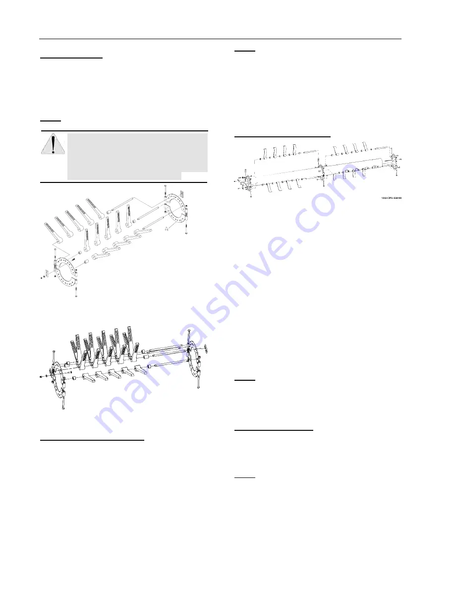
To adjust rubber flail clusters to row spacing, see Figure
17 and Figure 18. Loosen the disc clamp plates (A);
slide clusters so they are exactly centered on the row.
Retighten the disc clamping plates, making sure the gap
between the plates is equal and in line with the other
clusters.
NOTE:
For equal gap, tighten side with spacer washers
then tighten other side so it is equal.
CAUTION: KEEP WELL CLEAR OF MOVING
PARTS. BE SURE TO SHUT OFF THE
TRACTOR AND PLACE KEY IN YOUR
POCKET WHILE MAKING ADJUSTMENTS.
WAIT FOR ALL MOVEMENT TO STOP
BEFORE APPROACHING MACHINE.
Figure 17 - Rubber Flail Cluster (6 Pin).
Figure 18 - Steel Flail Cluster (8 Pin).
R
EPLACING
R
UBBER
F
LAILS
Frequently check flails. If any vibration occurs, check for
broken or damaged flails. Also check build-up that may
cause an unbalanced condition or extreme flexing of
rubber flails. For best service clean out mud build-up
frequently.
To replace flails, see Figure 17 and Figure 18
1.
Remove 3/8 inch carriage bolts and lock nuts that
hold the pin clips. Loosen, drive off taper, and
remove both clips. Slide pin to one side and
remove spacers and flails as needed.
NOTE:
Spacers and flails must be replaced in the same
sequence as they were removed. If only single flails are
exchanged, it is better to also replace the flail directly
opposite to maintain balance.
2.
After flails and spacers are replaced, install pin clip
by driving firmly in place with a flat piece of steel
and hammer into its position on the flail pin.
Tighten the 3/8 inch carriage bolts and lock nuts
securely on all pins.
R
EPLACING
S
TEEL
F
LAILS
Figure 19 - Steel Flail Cluster
Frequently check flails. If any vibration occurs, check for
broken or damaged flails, also check build-up that may
cause an unbalanced condition.
The steel flail pins are held in place by 5/8 inch-11 x
1-1/4 inch grade 5 bolts on each end of the 1 inch
diameter pin (see Figure 19). These bolts are held with
a retaining plate that captures the bolt head to insure
the retention of the bolt during operation. Remove this
plate and then remove bolt. (An impact wrench works
best)
1.
Remove the entire pin, with the flails and spacers,
from between the plates. Replace flails as needed.
2.
Before reinstallation, clean the bolt and the pin.
Use Locktite 271 or better when the bolts are
reinstalled. Torque these 5/8 inch -11 x 1-1/4 inch
bolts to 150 ft-lbs. Make sure the bolt retaining
plate is reassembled after the bolts have been
torqued.
NOTE:
Spacers, flails and center mounting plate must
be replaced in the same sequence as they were
removed. If only single flails are exchanged, it is better
to also exchange the flail directly opposite to maintain
balance.
D
RIVE
B
ELT
T
ENSION
Drive belts are tensioned by spring loaded idlers (see
Figure 20 and Figure 21). The compression springs are
compressed to 4.50 inches (see decal that is on the
machine).
NOTE:
These drives should be checked frequently and
re-tensioned immediately if any belt slippage occurs.
Do
not over-tighten.


