1222AHS OPERATORS MANUAL – FIELD OPERATIONS & ADJUSTMENTS
23
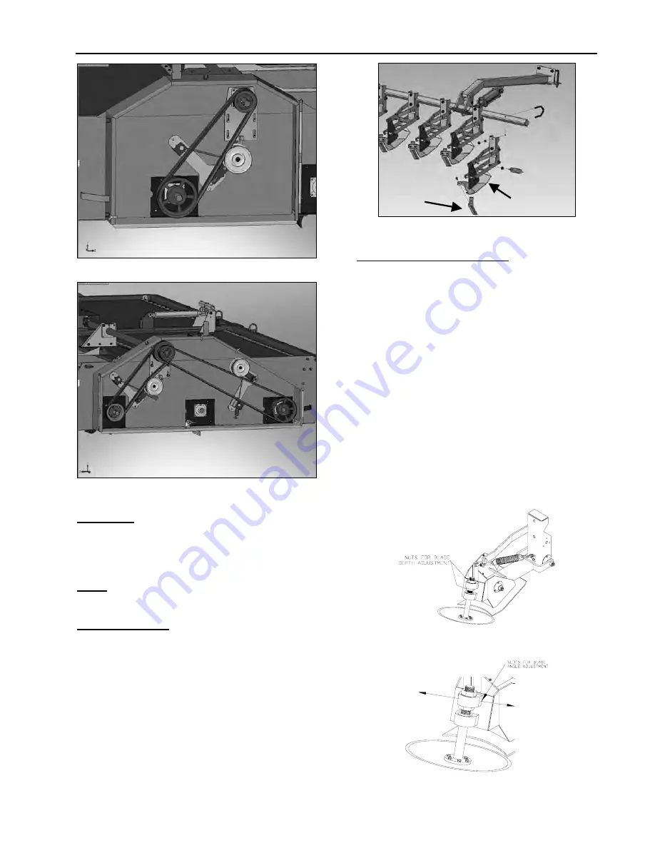
Figure 20 - RH Drives, Steel Flails.
Figure 21 - LH Drives, Steel Flails
S
CALPERS
1.
Adjust the scalper shoe (Figure 22, Item 1) so it is
parallel with the ground or tipped up slightly in
front. To perform, install the stops on the lift
cylinders.
NOTE:
The cylinders extend to raise and retract to
lower.
K
NIFE
S
CALPERS
1.
Make sure the tension spring is attached to the
scalper assembly. The tensions spring should hold
the scalper shoe firmly to the ground
3.
The scalper knife (2) should be set so it is parallel
and straight with the edge of the shoe. The
recommended initial setting is 1/4 inch to 3/8 inch.
Run the machine in the field and get one row
adjusted to the desired setting. Once the first row
is adjusted, set the other row settings to match.
Figure 22 - Knife Scalper Adjustment
M
ECHANICAL
D
ISC
S
CALPER
1.
Adjust the spring tension with the nuts on the
eyebolt (Figure 23).
2.
The depth of cut is adjusted by loosening the set
screws on the lower bearing and moving the two
jam nuts on the scalper shaft, sliding the shaft up
or down to attain the desired depth of cut, and then
re-tightening the jam nuts and set screws. The
distance from the bottom of the shoe to the lowest
point of the disc is generally between 3/4 to 1.0
inch. See Figure 23.
3.
The side-to-side angle of the blade can be
adjusted by loosening the two bolts on the top
bearing and moving the bearing in the slots on the
mounting plate. Re-tighten the bolts when finished.
The top bearing is positioned at the factory in the
center of the slots. See Figure 24
4.
Run the machine in the field and get one row
adjusted to the desired setting. Once the first row
is adjusted, set the other row settings to match.
Figure 23 - Mechanical Disc Scalper Depth Cutting
Adjustment
Figure 24 - Mechanical Disc Scalper Blade Angle
Adjustment
2
1


