17
MAINTENANCE SECTION
3. Whenever grasping a tool or part in a vise, always use
leather--covered or copper--covered vise jaws to protect
the surface of the part and help prevent distortion. This
is particularly true of threaded members and housings.
4. Except for bearings, always clean every part and wipe
every part with a thin film of oil before installation.
5. Apply o--ring lubricant to all o--rings before final
assembly.
6. Check every bearing for roughness. If an open bearing
must be cleaned, wash it thoroughly in a clean, suitable
cleaning solution and dry with a clean cloth.
Sealed or
shielded bearings should never be cleaned.
Work
grease into every open bearing before installation.
Assembly of the Throttle Mechanism
1. If the Trigger Assembly (3A) was removed, insert the
shaft of the Trigger into the Motor Housing (1) and
push it all the way into the trigger recess in the
Housing until it stops.
2. Using long reach needle nose pliers to hold the Trigger
Retainer (3B), insert the Retainer into the inlet bushing
opening and install the straight leg of the Retainer in
the hole through the shaft of the Trigger.
3. Install the Inlet Bushing Bezel (6), convex end leading,
onto the Inlet Bushing Assembly (4). Bring the convex
end into contact with the hex at the inlet end of the
Bushing.
4. Spread the opening slightly on the Inlet Bushing
Retainer (7) and install it around the Inlet Bushing with
the tab end nearest to the bushing hex and against the
Bezel.
5. Grasp the hex of the Inlet Bushing in leather--covered
or copper--covered vise jaws with the throttle valve
opening upward.
6. Insert the Throttle Valve Spring (8B), large end
leading, followed by the Throttle Valve (8A), long
stem end trailing, into the valve opening.
7. Place the Throttle Valve Seat (8C) followed by the
Valve Seat Support (8D) in the opening against the
Valve.
8. Using snap ring pliers while compressing the Throttle
Valve Spring and moving the Seat and Support inward,
capture the components by installing the Valve Seat
Retainer (8E) in the Bushing internal groove.
9. Moisten the Inlet Bushing Seal (8F) with o--ring
lubricant and install it on the exterior of the Inlet
Bushing.
10. Remove the assembled Bushing from the vise jaws. If
the Inlet Bushing Screen was removed, use a flat faced
dowel slightly less than 1/2” in diameter to push the
new Screen into the opening at the hex end of the
Bushing.
Assembly of the Motor
1. Place the Front End Plate (17) on the splined shaft of
the Rotor (15) with the bearing recess away from the
rotor body.
2. Place the Front Rotor Bearing (19) onto the shaft and
using a sleeve or piece of tubing that contacts the inner
race of the Bearing, press the Bearing onto the shaft
until the Front End Plate nearly contacts the rotor body.
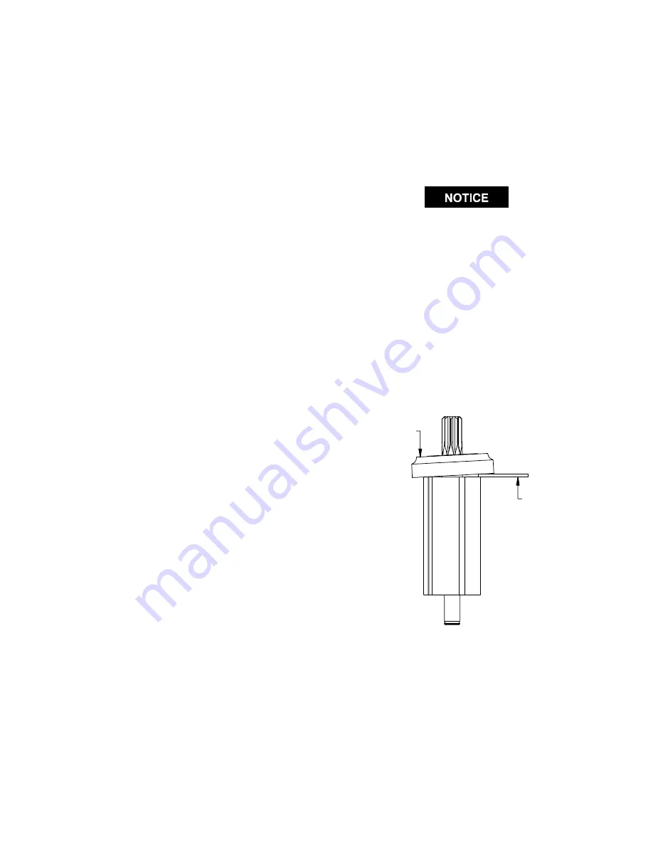
In the following step, the measurement must be
made at the end corner of the large rotor body.
3. The clearance between the Front End Plate and Rotor
is critical. While pressing down with your finger on the
outer edge of the Front End Plate on the bearing side,
insert a 0.004” (0.1 mm) feeler gauge between the face
of the rotor body and the face of the End Plate at a
point that is 180 degrees from where the pressure is
applied. Refer to Dwg. TPA1740. To increase the gap,
support the End Plate and lightly tap the rotor shaft
with a plastic hammer; to decrease the gap, press the
Bearing farther onto the rotor shaft.
Measurement of Front End Plate Clearance
(Dwg. TPA1740)
PRESSURE
FEELER
GAUGE
4. Wipe each Vane (16) with a light film of IRAX No. 10
Oil and place a Vane in each slot in the Rotor.
5. One end of the Cylinder Assembly (13) has a notch
that breaks the outer wall and end face of the Cylinder.
With that end trailing, install the Cylinder Assembly
over the Rotor and Vanes against the Front End Plate.
Make certain the Cylinder Alignment Pin (14) enters
the hole in the Front End Plate.
Содержание RG1AA
Страница 13: ...13 SERIES RG2 DRILLS Dwg ATP29 1 ...
Страница 20: ......


