


4
2.
CONTROL PANEL
* Warning the flue analysis mode must only be selected by a qualified service engineer.
ON/OFF
RESET
COMFORT
11
22
33
44
55
66
77
88
9 9
10 10
11 11
12 12
13 13
14 14
15 15
16 16
17 17
18 18
1919
2020
2121
22
22
23
23
24
24
99
66
12
12
I
36
37
30
26
32
29
33
34
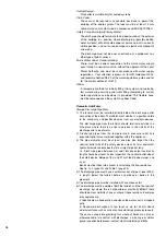
Control panel
(Fig. 2.1)
26
. -
On/off
push button
27
. -
Reset
push button
28
. - domestic hot water function and
COM-
FORT
tank on/off button
29
. - burner operation green indicator light
30
. - red indicator lock-out light
31
. - yellow indicator -
Comfort
button
32
. - Central Heating control knob
stop/mini/maxi
33
. - DHW control knob /mini/maxi
34
. - Increasing button
+
35
. - Reducing button
-
36
. - Menu button
37
. - Pressure gauge
46
. - Time clock
48
. - Display
35
27
28
31
48
46
F
IG
. 2.1
USER INSTRUCTIONS
Connecting bracket
Taps shown in Open position (Fig. 2.2)
39 :
Gas service tap
40 :
Water service tap
41
: Central heating flow isolating valve
42 :
Central heating return isolating valve
43 & 44
: Filling taps
45
: Filling loop
Fig. 2.2
41
42
43
44
45
39
40


