030-713-C0 Rev A WC
Page 7 of 23
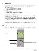
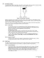
3.1.2 LEDs
The CXCM has three LEDs located on the front panel. These are used to display the alarm status of the power
system, CXCM progress and status during startup, and file transfers.
3.1.2.1 Alarm
Conditions
The CXCM illuminates the LED that corresponds to the system alarm status. The following
show the corresponding alarm status for each LED color:
Green
– OK, no alarms present
Yellow
– Minor alarm is present (no major alarms)
Red
– Major alarm is present.
Only one LED is illuminated at a time during alarm conditions.
3.1.2.2
Progress and Status Indication
The LEDs are also used in the following situations:
Base unit validation
– all three LEDs are on at the same time.
File transfer
– when recovering from invalid firmware application – the red LED is illuminated.
3.1.3 Reset
A reset button is located on the front panel for restarting the CXCM’s microprocessor. It takes approximately 15
seconds before the display reappears after pressing the reset button.
NOTE: Refer also to the software manual – always select the shutdown menu item before pressing the reset button.
3.1.4 Ethernet
Port
The Ethernet port is designed for CXCM connection to a user supplied network (TCP/IP secured by user) via a
rear panel RJ-45 jack and a standard network cable.
Local access (e.g. laptop computer) is also possible from the Ethernet port connection using a standard network
crossover cable.
3.1.5
RS-232 Serial (Craft) Port
Local access to the CXCM is possible through a front panel RS-232 serial port; using a null modem cable. The
communication protocol supports a web interface (via Microsoft® Internet Explorer 6 or greater). The remote
screen display is an enhanced version of the CXC’s front panel display.
3.2
Analog Input Channels
The CXCM has analog input channels for voltage, current, and temperature.
3.2.1 Voltage
Inputs
Two voltage input channels, V1 and V2, provide monitoring of discharge and charge voltage. The CXCM software
is pre-configured to monitor V2 for both load and battery voltage. V2 is used as the system reference for rectifier
float voltage, low voltage disconnect (LVD), system high voltage alarm, and system low voltage alarm. V1 is
available for additional voltage measurements.
3.2.2 Current
Inputs
The CXCM software is pre-configured to monitor I1 for load current using an external 50mV current shunt.
3.2.3 General-Purpose
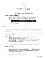
A set of terminals are provided to monitor a bi-voltage signal that may vary in either polarity from zero;
e.g., +/-60Vdc.
Содержание ALPHA OUTBACK ENERGY Cordex 48-1kW
Страница 1: ...Cordex 48 1kW 19 Shelf Flush Mounting Up To 3000W With Distribution 030 713 B2 ...
Страница 14: ...This page intentionally left blank ...
Страница 38: ...03071305B__ sch 1 Mon May 14 15 17 29 2007 ...
Страница 39: ...03071305B__ sch 2 Mon May 14 15 17 32 2007 ...
Страница 44: ...This page intentionally left blank ...


