96
6411-022
1. Set the meter selector to the OHMS position.
2. Connect the red tester lead to one spade end of the
fuse; then connect the black tester lead to the other
spade end.
3. The meter must show less than 1 ohm resistance. If
the meter reads open, replace the fuse.
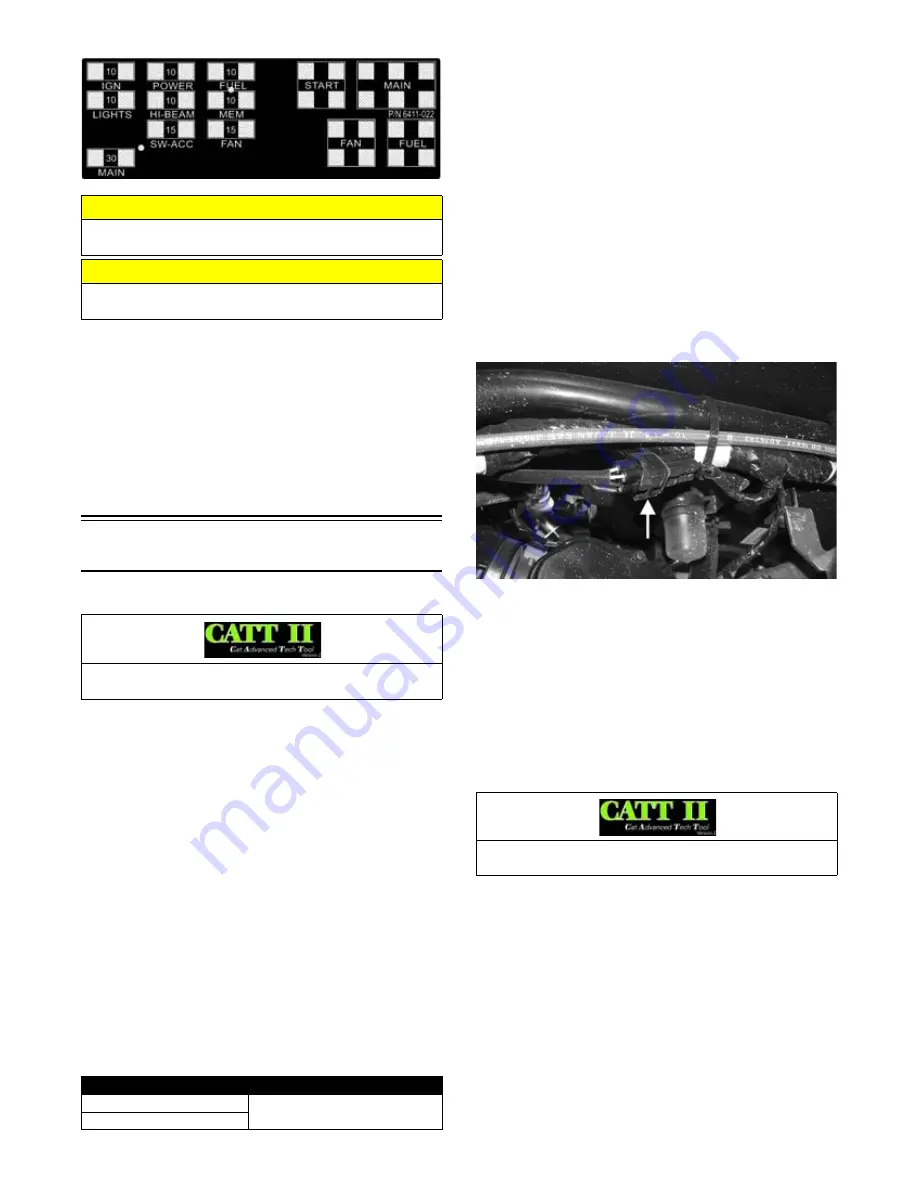
NOTE: Make sure the fuses are returned to their
proper position according to amperage. Refer to the
fuse block decal for fuse placement.
EFI Sensors/Components
FUEL INJECTOR
Voltage
Remove the connector from the fuel injector. Place the
red meter lead to the orange wire and black meter lead to
ground. With the ignition switch in the on position the
meter must read battery voltage.
Resistance
With the connector still removed from the injector, place
the red meter lead to either terminal; then connect the
black tester lead to the other terminal. Reading is typi-
cally 12 ohms ± 10% (500/1000) or 9.78-10.82 ohms
(700).
NOTE: If voltage is not present, troubleshoot the
battery, connector pins, wiring harness, fuses, or
relay. If resistance is not present or largely out of
specification, replace the injector.
CRANKSHAFT POSITION (CKP)
SENSOR
1. Set the meter selector to the OHMS position and test
as follows.
NOTE: The battery must be at full charge for the
voltage test.
2. Set the meter selector to the AC Voltage position.
3. Connect the red tester lead to the blue wire; then con-
nect the black tester lead to the green wire.
4. Crank the engine over using the electric starter. The
meter should read 2.0 or more.
OXYGEN (O2) SENSOR
The sensor is located in the exhaust pipe.
NOTE: The ambient temperature of the engine and
in the intake and exhaust system must be at room
temperature (approximately 68° F) when performing
this test or an incorrect reading will occur.
1. On the right side of the ATV, unplug the connector.
CF735A
2. On the sensor side of connector, connect the black
(negative) test lead to one white wire pin; then con-
nect the red (positive) test lead to the other white
wire pin.
3. With the meter in the OHMS position, the reading
should be between 6.7-10.1 ohms.
NOTE: If the meter does not read as specified,
replace sensor.
MANIFOLD ABSOLUTE PRESSURE
(MAP) SENSOR
1. Disconnect the MAP connector from the sensor
located on top of the throttle body.
2. Select DC Voltage on the tester and turn the ignition
switch to the ON position.
3. Connect the black tester lead to the black/pink wire
and the red tester lead to the orange/blue wire. The
meter should read 4.5-5.5 DC volts. If the meter does
not read as specified, check the ECM connector or
wiring.
CAUTION
Always replace a blown fuse with a fuse of the same
type and rating.
CAUTION
Always disconnect the battery when performing resis-
tance tests to avoid damaging the multimeter.
Component data can be tested using the CATT II. Utilize
the Test screen.
WIRE COLOR
RESISTANCE
Red to White
500 Ohms
Black to Brown
Component data can be retrieved using the CATT II. Uti-
lize the Sensor Data screen.
Содержание VLX 70002017
Страница 1: ...2017 S SERVICE ERVICE MANUAL ANUAL www arcticcat com...
Страница 137: ...136 NOTES...


