104
5. Depress the starter button and observe the multimeter.
NOTE: If battery voltage is indicated, replace the
starter relay. If no voltage is indicated, proceed to Power
Distribution Module (PDM) check in this section.
Electronic Control Module
(ECM)
The electronic control module (ECM) is located beneath
the seat near the battery.
NOTE: The ECM is not a serviceable component. If
the unit is defective, it must be replaced.
The ECM is rarely the cause for electrical problems;
however, if the ECM is suspected, substitute another
ECM of the same part number to verify the suspected one
is defective.
Codes can be cleared by following the procedures located
in EFI Diagnostic System in this section.
NOTE: If the throttle body, ECM, TPS, or ISC are
replaced, the EFI system must be synchronized. Use
the following procedure.
1. With the key off, depress throttle lever to Wide Open
Throttle (WOT).
2. Place the ignition key in the ON position and wait for
10 seconds.
3. Release the throttle lever and wait an additional 10
seconds.
4. Turn the key to the OFF position and allow the gauge
to shut off.
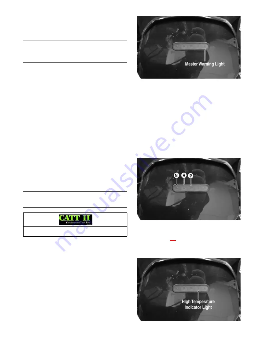
Indicator Display
Master Warning Light
The Master Warning Indicator light located on the indica-
tor display will illuminate and/or show a sequence of
flashes to indicate a malfunction. The sequence of flash
codes will continue until the malfunction is corrected and
the code cleared.
CF714B
If the Master Warning Light illuminates a flash sequence
of one second ON and one second OFF, a tip-over has
been detected or there are multiple system malfunctions.
If a tip-over has not occurred, use the CATT II diagnostic
tool to determine the specific malfunction/s.
To clear a flash sequence if a tip-over has occurred, move
the ATV to an upright position; then turn the key switch
to the OFF position for 30 seconds then back to the ON
position. If a malfunction persists, see Tilt Sensor.
Gear Position Lights
If all three gear position lights (N), (R), and (P) flash a
sequence of one second ON, one second OFF, the gear
position sensor/wiring is faulty or disconnected. See
Gear Position Switch.
CF714D
NOTE: During normal operation, no indicator dis-
play lights will illuminate when the gear shift lever is
set to the HIGH or LOW gear positions. (N), (R), and
(P) will illuminat
e i
e individually when the gear shift
lever is set to those respective positions.
High Temperature Indicator Light
CF714E
Component data can be retrieved using the CATT II. Uti-
lize the Sensor Data screen.
Содержание VLX 70002017
Страница 1: ...2017 S SERVICE ERVICE MANUAL ANUAL www arcticcat com...
Страница 137: ...136 NOTES...


