background image

16

FI464A

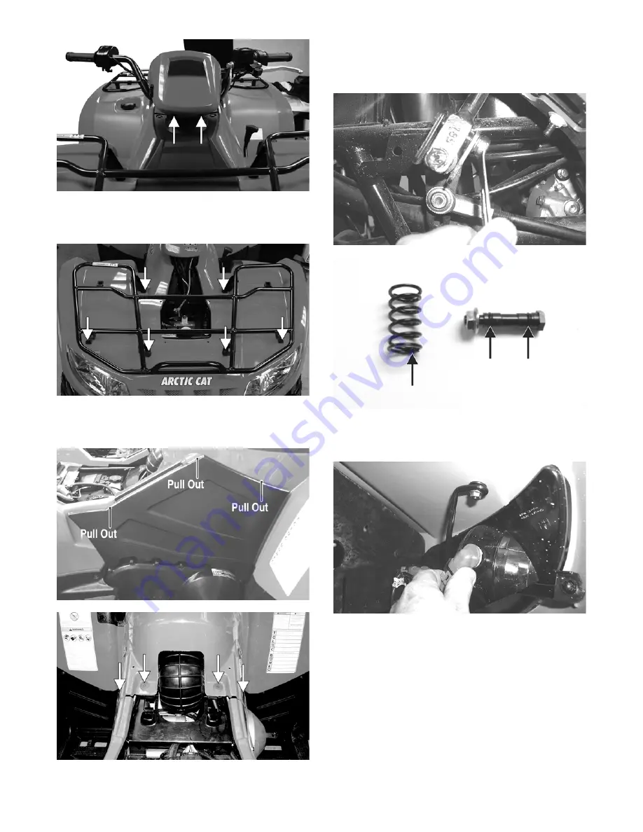
5. Remove  the  cap  screws  and  lock  nuts  securing  the

front rack to the frame; then remove the front rack.

Account for the grommets and bushings.

FI469A

6. Remove the side panels by pulling on them to release

the  tabs  from  the  body;  then  remove  the  screws

securing the rear of the front panel to the frame.

CF237A

FI470A

7. Remove the left and right footwells; then remove the

shift knob. Remove the shift lever pivot axle nut and

remove the axle and shift lever. Account for a spring

and two O-rings.

CD779

CD780A

8. Disconnect four headlight connectors and secure the

wires out of the way; then disconnect the wires to the

front accessory plug.

CD681

9. Rotate the handlebar to the full-left position; then lift

and slide the panel to the rear and lift the rear up to

clear the handlebar.

Содержание VLX 70002017

Страница 1: ...2017 S SERVICE ERVICE MANUAL ANUAL www arcticcat com...

Страница 2: ...Headlights Taillight Brakelight 28 Troubleshooting 30 Engine Transmission 31 Specifications 31 Troubleshooting 32 Removing Engine Transmission 34 Servicing Engine 38 Installing Engine Transmission 79...

Страница 3: ...possibility of damaging part or parts of the ATV The symbol NOTE identifies supplementary information worthy of particular attention The symbol AT THIS POINT directs the technician to cer tain and sp...

Страница 4: ...Rear Drive 45 in lb 5 Pinion Housing Differential Housing 23 31 Differential Housing Cover Differential Housing 23 31 Input Shaft Assembly Differential Housing 23 31 DRIVE TRAIN COMPONENTS cont Part P...

Страница 5: ...27 36 7 52 70 7 77 104 7 3 4 1 28 38 1 53 72 1 78 106 1 4 5 4 29 39 4 54 73 4 79 107 4 5 6 8 30 40 8 55 74 8 80 108 8 6 8 2 31 42 2 56 76 2 81 110 2 7 9 5 32 43 5 57 77 5 82 111 5 8 10 9 33 44 9 58 7...

Страница 6: ...aking the ATV out of storage and correctly preparing it will assure many miles and hours of trouble free riding Use the following procedure to prepare the ATV 1 Clean the ATV thoroughly 2 Clean the en...

Страница 7: ...re available 5 In a pan larger than the element with a mild deter gent dish soap and water wash all the dirt and oil off by squeezing the element not twisting it wring ing out or twisting the filter c...

Страница 8: ...djuster dial counterclockwise until proper valve tappet clearance is attained NOTE Refer to the appropriate specifications in CHECKING for the proper valve tappet clearance NOTE Rotating the valve adj...

Страница 9: ...he plug free of carbon ATV 0051 Adjust the gap to correct specification see General Infor mation for proper type and gap Use a feeler gauge to check the gap ATV0052 A new spark plug should be tightene...

Страница 10: ...ur the specified amount of the recom mended oil in the filler hole Install the oil level stick filler plug 7 Start the engine while the ATV is outside on level ground and allow it to idle for a few mi...

Страница 11: ...ug NOTE If the differential rear drive lubricant is contaminated with water inspect the drain plug fill plug and or bladder 6 Install the fill plugs then tighten to 16 ft lb Install the level plugs an...

Страница 12: ...the res ervoir located beneath the seat CF295A CF723 2 Compress the brake lever pedal several times to check for a firm brake If the brake is not firm the system must be bled 3 To bleed the main brake...

Страница 13: ...sted automatically as the brake pads wear The only maintenance that is required is replacement of the brake pads when they show excessive wear Check the thick ness of each of the brake pads as follows...

Страница 14: ...p screws securing the CVT cover not ing the location of the different lengthed cap screws for installing purposes Account for the fibrous washers then using a rubber mallet gently tap on the cover tab...

Страница 15: ...point the M6 x 1 0 cap screw that was used to separate the sheaves of the driven clutch can be removed 3 With the vehicle in neutral rotate the V belt and clutches counterclockwise until the V belt i...

Страница 16: ...ked periodi cally for damage bends cracks deterioration broken components and missing components Front Body Panel Side Panels REMOVING 1 Remove the reinstallable rivets securing the radiator access co...

Страница 17: ...anel to the frame CF237A FI470A 7 Remove the left and right footwells then remove the shift knob Remove the shift lever pivot axle nut and remove the axle and shift lever Account for a spring and two...

Страница 18: ...shings are in place then place the front rack into position and secure with the cap screws and lock nuts Tighten securely 4 Install the footwells and footrests Tighten securely 5 Install the cap screw...

Страница 19: ...ear body panel to each footwell CF669 3 Remove two machine screws securing the battery cover and remove the cover CD687A 4 Disconnect the battery negative cable first then remove the battery 5 Disconn...

Страница 20: ...panel has not been installed see Front Body Panel Side Panels in this sec tion 6 Place the seat into position making sure it locks securely Indicator Display REPLACING 1 Remove the two reinstallable r...

Страница 21: ...cket to the steering post then move the handlebar and gauge out of the way Account for four handlebar caps CF659 7 Remove two cap screws securing the upper steering post bearing to the frame Account f...

Страница 22: ...he frame with two cap screws Tighten to 20 ft lb AL600D 2 Place the upper steering post mounting blocks into position then insert the two shoulder screws through the frame and thread them into the ste...

Страница 23: ...65A Handlebar Grip INSPECTING REMOVAL 1 Inspect the grip for wear cuts or cracks 2 Inspect the grip for deterioration CF747 3 If a grip is damaged cut the grip lengthwise using a sharp knife or box cu...

Страница 24: ...account for a bushing Note the position of the return spring for installing purposes AF678D INSTALLING 1 Place the return spring into the throttle control then place the bushing and actuator arm into...

Страница 25: ...all joint end out of the knuckle then remove the knuckle 9 Remove the snap ring from the knuckle then remove the bearing PR287A PR288 CLEANING AND INSPECTING 1 Clean all knuckle components 2 Inspect t...

Страница 26: ...nut 11 Install the wheel then using a crisscross pattern tighten the wheel nuts in 20 ft lb increments to a final torque of 40 ft lb steel wheel 60 ft lb aluminum wheel w black nuts or 80 ft lb alumi...

Страница 27: ...rm and shift lever then making sure the O rings are in place on the axle secure the shift lever to the arm with the existing axle and nut 2 Place the shift rod into position on the shift lever and sec...

Страница 28: ...sembly into position and install the lower cap screws Finger tighten only 2 Install the two flange bolts and lock nuts on the upper supports Tighten all hardware securely Footrests REMOVING 1 Remove t...

Страница 29: ...body and secure with torx head cap screws and any washers 2 Tighten the cap screws securely 3 Route the wiring harness over the rear frame then connect the three prong connector Seat REMOVING INSTALL...

Страница 30: ...uld be an average operating load on the ATV when adjusting the headlight aim 2 Measure the distance from the floor to the mid point of each headlight 3 Using the measurements obtained in step 2 make h...

Страница 31: ...ighten replace cap screws 4 Replace bearing 5 Replace tighten tie rod ends 6 Replace tires 7 Replace bushings 8 Tighten bolts nuts Problem Steering pulling to one side Condition Remedy 1 Tires inflate...

Страница 32: ...otector Tool 0444 252 Spanner Wrench 0444 240 Surface Plate 0644 016 Valve Clearance Adjuster 0444 255 V Blocks 0644 535 VALVES AND GUIDES Valve Face Diameter max intake exhaust 31 6 mm 27 9 mm Valve...

Страница 33: ...fouled 2 Magneto defective 3 ECM defective 4 Fuel injector obstructed 5 Valve clearance out of adjustment 1 Clean plug 2 Replace magneto 3 Replace ECM 4 Replace fuel injector 5 Adjust clearance Probl...

Страница 34: ...moke dirty or heavy Condition Remedy 1 Engine oil overfilled contaminated 2 Piston rings cylinder worn 3 Valve guides worn 4 Cylinder wall scored 5 Valve stems worn 6 Stem seals defective 1 Drain exce...

Страница 35: ...ngine transmission then drain the coolant 733 441A CD799A 7 Remove the air filter see Periodic Mainte nance Tune Up 8 Loosen the clamp securing the air intake duct to the air filter housing CF726A 9 D...

Страница 36: ...ctors from the TPS ISC valve fuel injector and MAP sensor Loosen the intake boot clamp then move the throttle body out of the way XR298A 14 Remove the clamp securing the cooling duct boot to the V bel...

Страница 37: ...he hoses out of the way One coolant hose is located on the outer water pump cover The second coolant hose is connected to the thermostat housing 20 Remove the cap screws securing the rear drivesh aft...

Страница 38: ...utput flange joint Block the engine up in this position CD811 28 Remove the first small boot clamp then remove the output flange and driveshaft from the rear drive cou pler CF728A CD813 29 Remove the...

Страница 39: ...ransmission does not have to removed from the frame for this procedure Removing Top Side Components A Valve Cover Rocker Arms B Cylinder Head Camshaft NOTE Remove the spark plug and timing inspec tion...

Страница 40: ...rankcase CC012D 7 Bend the washer tabs down and remove the two cap screws securing the sprocket to the camshaft then drop the sprocket off the camshaft CC013D 8 While holding the chain slide the sproc...

Страница 41: ...ecede this procedure 13 Loosen the clamp securing the coolant hose to the union then detach the hose 14 Remove the two nuts securing the cylinder to the crankcase CC023D 15 Lift the cylinder off the c...

Страница 42: ...stems valve faces and valve stem ends for pits burn marks or other signs of abnormal wear NOTE Whenever a valve is out of tolerance it must be replaced AT THIS POINT To service cylinder see Installin...

Страница 43: ...invert the cylinder head and remove the valves Measuring Valve Guide Bore 1 Insert a snap gauge 1 2 way down into each valve guide bore then remove the gauge and measure it with a micrometer 2 Accepta...

Страница 44: ...ve blowby indicates worn piston rings or an out of round cylinder Removing Piston Rings 1 Starting with the top ring slide one end of the ring out of the ring groove CC400D 2 Remove each ring by worki...

Страница 45: ...stall the lower oil control lower rail ring at 0 from the directional arrow then position the opening of the upper oil control upper rail ring 180 away from the piston direc tional arrow NOTE Note the...

Страница 46: ...found repair the surface using a cylinder hone see Inspecting Cylinder in this sub section 3 Place the cylinder on the surface plate covered with 400 grit wet or dry sandpaper Using light pressure mo...

Страница 47: ...ing Camshaft Runout NOTE If the camshaft is out of tolerance it must be replaced 1 Place the camshaft on a set of V blocks then position the dial indicator contact point against the shaft and zero the...

Страница 48: ...6D CC025 3 Lubricate the inside wall of the cylinder then using a ring compressor or the fingers compress the rings and slide the cylinder over the piston Route the cam chain up through the cylinder c...

Страница 49: ...t lb 11 Tighten the 8 mm nuts from step 9 to 18 ft lb and the 6 mm nuts to 8 5 ft lb then tighten the two cylin der to crankcase nuts from step 4 securely 12 With the timing inspection plug removed an...

Страница 50: ...g surface D Recessed side of the sprocket directed toward the cam lobes E Camshaft alignment pin and sprocket alignment hole smallest are aligned 17 Place the tab washer onto the sprocket making sure...

Страница 51: ...ace CD501 NOTE The adjuster shaft will be drawn into the tensioner as the adjuster screw is rotated clockwise The adjuster shaft tension will be released in step 25 24 Place the chain tensioner adjust...

Страница 52: ...n the cap screws from step 29 to 8 5 ft lb 31 Adjust valve tappet clearance see Periodic Mainte nance Tune Up 32 Place the two tappet covers into position making sure the proper cap screws are with th...

Страница 53: ...gear shift selector switch B CF680A 5 Remove the gear shift selector switch from the shift arm shaft Note the protrusion extending out the backside of the gear shift selector switch and the recess in...

Страница 54: ...he starter clutch gear assembly and washer PR441 CD939A CD940A 13 Remove the two starter gears from the crankcase not ing the direction of the gears for installing purposes then remove the two starter...

Страница 55: ...ckwise and it should turn freely If it moves or locks up both ways the starter clutch must be replaced 2 Inspect the starter clutch gear for chipped or missing teeth or discoloration scoring of the cl...

Страница 56: ...bearing bores REPLACING STATOR COIL CRANKSHAFT POSITION SENSOR 1 Remove the three cap screws securing the stator coil two cap screws securing the crankshaft position sen sor and one cap screw from th...

Страница 57: ...in removing then secure with the snap ring CD950A CD952A CD949 NOTE The sharp side of the snap ring should be facing outward 2 Install the water pump drive gear drive pin and the drive gear with the f...

Страница 58: ...ith red Loctite 271 and tighten to 8 ft lb PR433A CD934 6 Install the shift cam stopper spring and two washers thick washer closest to the nut then coat the threads on the mounting stud with red Locti...

Страница 59: ...5 ft lb CF729A 13 Place the water pump into position and secure with two cap screws Tighten to 8 ft lb NOTE Ensure the slotted water pump shaft is aligned with the groove in the counter balancer shaf...

Страница 60: ...asher then using a rubber mallet gently tap on the cover tabs to loosen the cover Account for two alignment pins and a gasket H1 017 2 If the support bearing in the V belt cover is in need of servicin...

Страница 61: ...locations shown Remove the gas ket H1 026 H1 029B NOTE For steps 8 13 refer to illustration H1 029A NOTE To aid in installing it is recommended that the assemblies are kept together and IN ORDER H1 02...

Страница 62: ...11 Remove the cap screw securing the oil pump drive gear B Account for a cap screw washer pin and spacer CC606 12 Using an impact wrench remove the cap screws securing the final drive carrier bearing...

Страница 63: ...the clutch assembly ATV1014 INSPECTING CLUTCH HOUSING 1 Inspect the clutch housing for burns grooving cracks or uneven wear 2 If the housing is damaged in any way the housing must be replaced DRIVE C...

Страница 64: ...he sheave plate into the movable drive sheave CF381 DRIVEN CLUTCH ASSEMBLY Disassembling 1 Secure the clutch spring compressor base in a work vise attached to a stable work table or work bench WC422A...

Страница 65: ...the sheave faces for cracks grooving or checking WC381 WC383 2 Inspect the cam shoes on the movable driven sheave for chipping excessive scoring or general condition WC384A NOTE Always replace the ca...

Страница 66: ...tall the spring over the hub of the movable driven sheave engaging the spring into the previously marked spring anchor hole WC391A 4 Place the cam over the spring and align the spring tip to the previ...

Страница 67: ...s flush and clear of the snap ring groove then install the snap ring making sure it is seated properly WC412 WC419 9 Turn the wing nut counterclockwise slowly allowing the cam to contact the snap ring...

Страница 68: ...and the washer Tighten the cap screw to 63 ft lb CD992 CD991 4 Place the washer A onto the oil pump driveshaft then grease the driven gear pin B and insert it into the oil pump driveshaft Install the...

Страница 69: ...posi tion on the crankcase then secure with the cap screws making sure the different lengthed cap screws are in their proper location Tighten to 8 ft lb 10 Place the driven pulley assembly into posit...

Страница 70: ...with fibrous washers making sure the dif ferent lengthed cap screws are in their proper loca tion Tighten the cap screws to 44 in lb CF683 Center Crankcase Components NOTE This procedure cannot be don...

Страница 71: ...ORDER PR787A 1 Remove the secondary driven shaft assembly A noting the location of the bearing locating pins Account for the bearing C ring PR787B 2 Remove the reverse idler gear assembly F Account fo...

Страница 72: ...t assembly NOTE Use a protective end cap to prevent damage to the crankshaft threads 11 Remove the cap screws securing the oil strainer cap then remove the cap 12 Remove the two cap screws securing th...

Страница 73: ...shaft until the gear firmly seats on the shoulder of the shaft MT011B 3 If installing the existing shaft start with the shims removed during disassembly or if installing a new shaft start with approxi...

Страница 74: ...aft threads and driven output shaft threads then using new nuts tighten the output shaft nut to 59 ft lb and the output yoke nut to 200 ft lb CRANKSHAFT ASSEMBLY NOTE The crankshaft and connecting rod...

Страница 75: ...h range must not exceed specifica tions COUNTERSHAFT GZ281A Disassembling 1 Remove the shift forks noting the positions for assembling then remove the high driven gear outer washer high driven gear hi...

Страница 76: ...reverse driven gear and washer then remove the washer A reverse driven gear B and needle bearing C H1 044 H1 045A H1 046A 6 Remove the reverse driven washer D then remove the low driven gear E H1 047A...

Страница 77: ...stall the reverse driven gear needle bearing C then the reverse driven gear B H1 046A 3 Install the outer reverse driven gear washer A then secure the reverse driven gear assembly with a new snap ring...

Страница 78: ...ring Using a propane torch heat the bear ing until the oil begins to smoke then slide the crankshaft assembly into place CC688 CC689 NOTE If heating the bearing is not possible the crankshaft can be i...

Страница 79: ...seated into the shift cams CC669 9 Install the reverse idler gear assembly noting the positioning of the two washers gear bushing and shaft CC668 10 Install the front and rear secondary driven shaft...

Страница 80: ...d forth to ensure no binding or sticking occurs 9 In a crisscross case to case pattern tighten the 6 mm cap screws from steps 6 7 to 10 ft lb NOTE Rotate the shafts back and forth to ensure no binding...

Страница 81: ...securely XR299A CF731A 8 Secure the engine and harness ground wires to the engine with the two starter motor mounting cap screws Tighten to 8 ft lb CF727A 9 Connect the stator coil and crankshaft posi...

Страница 82: ...ir cleaner housing then secure the inlet boot and throttle body to the air filter housing Install the air filter see Peri odic Maintenance Tune Up CD787 CF731A CD786 20 Connect the intake air temperat...

Страница 83: ...Place the battery into position in the battery compart ment then install the battery cables positive cable first Secure with the battery cover 28 Add proper amounts of engine transmission oil and cool...

Страница 84: ...f a code is flashing see EFI Sen sors Components in Electrical System 3 Make sure there is sufficient clean gas in the gas tank Throttle Body REMOVING 1 Turn the ignition switch to the OFF position th...

Страница 85: ...ng the intake manifold flange to the cylinder head Account for an O ring 12 Use tape to cover and seal the intake opening INSTALLING 1 Place a new O ring onto the intake pipe then posi tion the pipe o...

Страница 86: ...rack and fenders see Steer ing Body Controls 3 Using an absorbent towel under the hose disconnect the fuel hose from the fuel pump by compressing the release on the connector A Disconnect the fuel gau...

Страница 87: ...il pressure gauge Wipe up oil residue with a cloth 3 Start the engine and run at 3000 RPM With the oil temperature at 60 C 140 F the oil pressure gauge must read 1 2 1 5 kg cm2 17 21 psi NOTE If the o...

Страница 88: ...based automotive type antifreeze RADIATOR Removing 1 Drain the coolant by removing the drain screw found on the water pump Account for the washer XR318A NOTE Removing the radiator cap will help evacu...

Страница 89: ...ermostat does not open it must be replaced 3 Inspect all coolant hoses connections and clamps for deterioration cracks and wear NOTE All coolant hoses and clamps should be replaced every four years or...

Страница 90: ...b 4 Fill the engine transmission with the proper amount of recommended oil 5 Fill the cooling system with the proper amount of recommended coolant NOTE While the cooling system is being filled air poc...

Страница 91: ...ccessory usage are also reasons for battery discharge Maintenance Charging NOTE Use the CTEK Multi US 800 or the CTEK Multi US 3300 for battery maintenance charging Maintenance charging is required on...

Страница 92: ...rger connected to the battery for a minimum 1 hour after the Maintenance Charge Indicator D illu minates If the battery becomes hot to the touch stop charging Resume after it has cooled 7 Once the bat...

Страница 93: ...er lead to either terminal then connect the black tester lead to the other terminal 2 Resistance must be less than 1 ohm NOTE If the meter does not show as specified replace ignition coil NOTE Seconda...

Страница 94: ...than 1 ohm of resis tance replace the switch RESISTANCE HI Beam The connector is the yellow one next to the steering post To access the connector the steering post cover and the right side fender spla...

Страница 95: ...Set the meter selector to the OHMS position 2 Connect the red tester lead to one red yellow wire then connect the black tester wire to the other red yellow wire The meter must show less than 1 ohm 3...

Страница 96: ...VOLTAGE Brakelight NOTE Perform this test on the main harness side of the connector Also the ignition switch should be in the ON position and the brake either foot pedal or hand lever must be applied...

Страница 97: ...ester lead to the green wire 4 Crank the engine over using the electric starter The meter should read 2 0 or more OXYGEN O2 SENSOR The sensor is located in the exhaust pipe NOTE The ambient temperatur...

Страница 98: ...sensor then using Maxi Clips connect the red tester lead to the green red wire Connect the black tester lead to the pink black wire With the engine at idle the meter should read approximately 2 9 DC...

Страница 99: ...opening in the gas tank 5 Using duct tape or other suitable means cover the fuel pump opening INSPECTING 1 Inspect the fuel screen and blow clean with low pres sure compressed air 2 Move the float lev...

Страница 100: ...Note that the fuel pump runs momentarily and the fuel gauge indicates the proper fuel level 5 With the transmission in neutral and brake lever lock engaged start the engine and check for normal oper...

Страница 101: ...g the sensor after testing make sure the arrow marking is directed up CD705A THROTTLE POSITION SENSOR TPS Verifying TPS Adjustment Tool Before using the TPS adjustment tool verify its battery conditio...

Страница 102: ...ter With the vehicle off and the throttle plate fully closed the gauge should read 0 58 0 62 DC volts and at Wide Open Throttle it should read up to approximately 3 7 DC volts CF329A Adjusting 1 Loose...

Страница 103: ...replace the stator assembly Regulator Rectifier The regulator rectifier is located under the rear rack and rear fenders TESTING 1 Start engine and warm up to normal operating tem perature then connect...

Страница 104: ...crankcase then remove the starter motor Account for the wiring forms and an O ring INSTALLING 1 Apply a small amount of grease to the O ring seal on the starter motor then install the starter motor in...

Страница 105: ...e Master Warning Indicator light located on the indica tor display will illuminate and or show a sequence of flashes to indicate a malfunction The sequence of flash codes will continue until the malfu...

Страница 106: ...ange voltage Correct condition P0122 TPS Circuit Low SG Sensor or interconnect harness shorted to chassis ground Correct condition P0123 TPS Circuit High Sensor or interconnect harness open or shorted...

Страница 107: ...starter relay or interconnect harness intermittent or shorted to battery power Correct condition P0630 VIN Not Programmed or Incompatible Verify the Indicator Display and ECM part numbers are correct...

Страница 108: ...or rectifier 4 Replace battery Problem Battery overcharges Condition Remedy 1 Internal battery short circuited 2 Regulator rectifier resistor damaged defective 3 Regulator rectifier poorly grounded 1...

Страница 109: ...ront wheels 4 Pump up the hand brake then engage the brake lever lock 5 Remove and discard the cotter pin securing the hex nut then remove the hex nut and washer KX041 6 Release the brake lever lock N...

Страница 110: ...bolts Account for the lock nuts then move the shocks aside and secure them with a strap XR340 14 Remove the upper A arm lock nuts and cap screws then remove the A arms CF661 15 Push the axle shaft fir...

Страница 111: ...ssembly from the frame then shift the differential assembly forward enough to dis engage the front driveshaft from the output yoke CD857 20 Place the differential on its right side then remove it from...

Страница 112: ...ng a seal removal tool remove the input shaft seal Account for a spacer GC010 6 Remove the snap ring securing the input shaft bear ing then place the pinion housing in a press and remove the bearing G...

Страница 113: ...pressed air then lubricate with recommended grease GC009A 4 With the return spring over the shuttle shaft place the shuttle shaft with O ring into the differential housing XR352A XR354 5 Place the dow...

Страница 114: ...coupler fork shuttle shaft with O ring and spring differen tial only XR352A 2 Using a T 40 torx wrench remove the cap screws securing the differential cover 3 Using a plastic mallet tap lightly to re...

Страница 115: ...R359 3 Secure the pinion gear in a bearing puller then remove the pinion bearing using a press Account for a collar and a bearing CC879 4 Remove any reusable parts from the gear case hous ing then dis...

Страница 116: ...055 in shim on the gear case side of the ring gear assembly GC031A 2 Install the ring gear with shim in the gear case then while holding the pinion stationary rock the ring gear forward and back to de...

Страница 117: ...ture with the cover side up then install a dial indicator contacting the ring gear axle flange GC035 2 Zero the dial indicator then push the ring gear toward the dial indicator and release End play sh...

Страница 118: ...spring into the housing making sure the shaft O ring is positioned to the inside XR354 6 Install the shift fork assembly making sure the fork leg is facing upward Apply a small amount of oil to the ga...

Страница 119: ...the front dif ferential CF737A 5 Pull the rubber seal off the end of the cable housing then un thread the very next jam nut off the end of the cable housing Slide the cable through the slot on top of...

Страница 120: ...k the front differential for normal 2WD 4WD operation If adjustment is necessary recheck the set length at the cable housing bracket then adjust the screw and lock nut located on the shift lever CF740...

Страница 121: ...TE Always clean and inspect the drive axle components to determine if any service or replace ment is necessary 1 Using a clean towel wipe away any oil or grease from the axle components CF635 2 Inspec...

Страница 122: ...hould remain clipped in place 2 Swing the knuckle up and onto the drive axle then place the knuckle into place in the upper A arm Secure the knuckle to the A arm with a cap screw and a new lock nut Ti...

Страница 123: ...nch tighten the hub nut from step 4 to 200 ft lb then install and spread a new cotter pin making sure each side of the pin is flush to the hex nut NOTE If the cotter pin does not line up always tighte...

Страница 124: ...he ring gear with selected shim into the cover and measure the ring gear to thrust button clearance with a thickness gauge Clearance should be 0 020 0 040 in GC058A 3 If clearance is as specified remo...

Страница 125: ...appropriate hub retaining wrench tighten the hub nut from step 4 to 200 ft lb then install and spread a new cotter pin making sure each side of the pin is flush to the hex nut NOTE If the cotter pin d...

Страница 126: ...lebar DE058A INSPECTING 1 Inspect the pin securing the brake lever for wear 2 Inspect the brake lever for elongation of the pivot hole 3 Inspect the reservoir for cracks and leakage 4 Inspect the banj...

Страница 127: ...int This increases the chance of vapor lock reducing braking power and increasing stopping distance 3 Remove the brake hose from the caliper and close the bleed screw then remove the caliper 4 Compres...

Страница 128: ...Do not wipe dry 2 Inspect the brake pads for damage and excessive wear NOTE For measuring brake pads see Periodic Maintenance Tune Up 3 Inspect the brake caliper housings for scoring in the piston bo...

Страница 129: ...de of the brake hose fitting and install it on the caliper Tighten to 20 ft lb 8 Fill the reservoir then bleed the brake system see Periodic Maintenance Tune Up 9 Install the wheel then using a crissc...

Страница 130: ...coupling 4 Replace joint 5 Replace gear s 6 Replace gears pinions 7 Replace gear s 8 Replace axle 9 Replace axle Problem Braking poor Condition Remedy 1 Pad worn 2 Pedal free play excessive 3 Brake fl...

Страница 131: ...nut securing each rear shock absorber to the frame and lower A arm Account for bushings and sleeves from each XR340 4 Using Spring Tool compress the shock absorber spring remove the retainer and remo...

Страница 132: ...ring the tie rod end to the knuckle then remove the tie rod end from the knuckle XR367 7 Remove the cap screws securing the ball joints to the knuckle PR203 8 Tap the ball joints out of the knuckle th...

Страница 133: ...frame mounts and secure with the cap screws Only finger tighten at this time CF661 3 Route the brake hose through the upper A arm shock absorber mount then secure the hose to the A arm with a brake h...

Страница 134: ...the shock absorber to the frame and lower A arm then remove the shock absorber 7 Remove the cap screws securing the boot guard to the lower A arm AF934 8 Slide the hub out of the knuckle and set asid...

Страница 135: ...heels and Tires TIRE SIZE The ATV is equipped with low pressure tubeless tires of the size and type listed in General Information Do not under any circumstances substitute tires of a different type or...

Страница 136: ...lem Suspension too soft Condition Remedy 1 Spring s weak 2 Shock absorber damaged 3 Shock absorber preload too low 1 Replace spring s 2 Replace shock absorber 3 Adjust shock absorber preload Problem S...

Страница 137: ...136 NOTES...

Страница 138: ...Printed in U S A Trademarks of Arctic Cat Inc Thief River Falls MN 56701 p n 2261 427 2017 Arctic Cat Inc Effective May 2017...

Отзывы: