On the products with
icematic, water valve group is reached after the co
mpressor rear cover
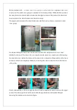
is removed. The water valve group is consisted of two main sections. While the first section is
the area shown in red and which is located on the upper section of the product, the other and
lower section is the cabin bottom area shown in orange.
The upper section consists the water intake area and the lower section is consisted of water
valve group.
For disassembling the water valve on the lower section, the compressor rear cover must
initially be removed. The water valve is connected to the panel via a single screw. Removing
the relevant screw enables the release of the water valve connection. Disassembly of the lower
section is carried out completely finally by removing the socket connection from the bottom
of the cabin.
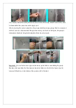
Firstly, disassembly of the water pipe on the rear wall is required in order to remove the upper
section. The water pipe fixed on the rear wall with pipe holders is demounted through
removing the holders as shown in the figure.
Содержание K60365
Страница 53: ...50 14 ELECTRICAL CIRCUIT DIAGRAM...


