11
!
In addition to the guide below it is essential that the Important information section is read and
understood and that you have all the necessary components (shown on page 9 or 10) before
commencing installation. Failure to install the product in accordance with these instructions may
adversely affect the warranty terms and conditions. Do not undertake any part of this installation
unless you are competent to do so. Prior to starting, ensure that you are familiar with the necessary
plumbing regulations required to install the product correctly and safely.
Dream DCV valve installation
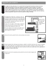
1
If installing the product into a solid wall, chase out
a suitable recess in the wall to receive the valve and
pipework. If installing the valve in a concealed panel
mounted situation, in most cases it will be necessary
to first install a suitable sound fixing in the cavity
area before fixing the valve.
A hole of 117mm wide x 135mm high is required to
enable removal of the mortar guard and to allow
for any future maintenance of the valve.
The valve needs to be mounted to the depth shown
opposite. The distance between the ¾ inch inlet
pipe connections is 140mm.
2
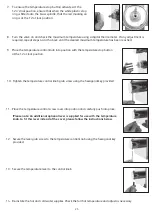
Remove the mortar guards from the valve assembly and set aside.
3
Prepare suitable 22mm inlet pipe work ending in suitable ¾ inch BSP connections and construct a suitable
15mm outlet supply pipe to the desired location for the wall outlet, fixed head or bath overflow outlet.
4
Place the valve into the required position within the wall and mark and prepare the
fixing points.
85mm max. to finished/tiled wall surface
70mm min from
back face of valve
to finished/tiled
wall surface
(10mm allowance
for tiles)
!
For divert valves, the top outlet feeds to the fixed head and the side outlet feeds to the adjustable kit
wall outlet or bath overflow filler.


