background image

15

14

3

Panel Description

Panel Description

Selection soft keys

PROFESSIONAL


INNOVATIVE    BRANDING


SERVICE

PROFESSIONAL


INNOVATIVE    BRANDING


SERVICE

1

4

Panel Description

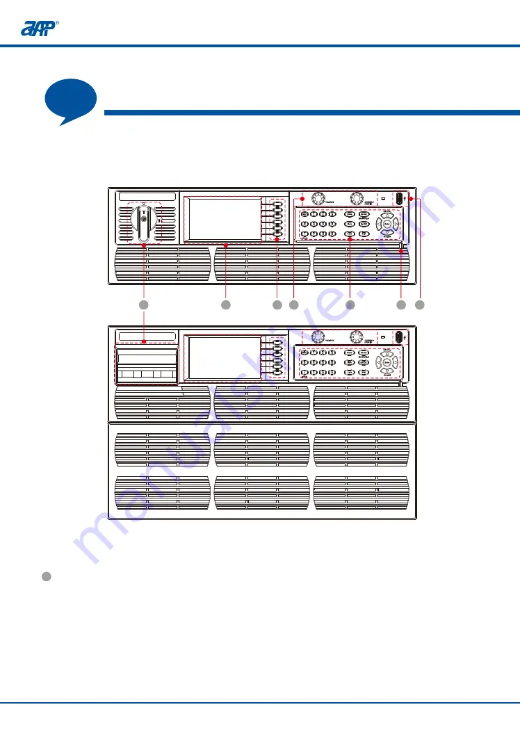
4.1 Front Panel Description

2

1

Color touch screen

Power Switch

For 3U models, rotate power switch clockwise to turn on the unit.  Rotate power switch count-

erclockwise to turn off the unit. The 6U product is fitted with a mains input circuit breaker on 

the top left-hand side of the front panel. The power off position of the circuit breaker handle 

is marked "O". The power on position of the circuit breaker is marked " I".

The color LCD touch screen displays all settings, measurements, menus and warning message.

It may also be used to enter parameter values and settings by using its touch screen function. 

The user can use his fingertip or the built-in stylus inside the front panel directly to control the 

unit. 

There are six soft keys located along the right hand side of the LCD screen. The labels of these

key will change when selecting different screens. To select any of these soft keys, either press 

the area on the touch LCD or press the actual button on the right hand side of the screen.

4

Voltage/Current & Power setting knob

Turning the shuttle to right (clockwise) increments a selected field value. Turning it to the left 

(counter clockwise) decrements a selected field value. The setting value will be effective 

immediately without pressing the [Enter] key.

The default location of the cursor after rotating knob is at the first digit after the decimal point.

All  the  yellow  characters  can  be  set.  To  enter  parameter  values  using  the  LCD  screen, 

after touching the setting zone. An on-screen decimal keypad will pop up. Touch the relevant 

number keys in screen to enter a value and press the [ Enter] key when done. To abort, press 

the [ESC] key instead and the previous value will appear.

1

2

3

4

5

7

6

Содержание APM-SP-VDC-3U Series

Страница 1: ...APM TECHNOLOGIES PROFESSIONAL INNOVATIVE BRANDING SERVICE High Power DC Power Supply en apmtech cn User Manual...

Страница 2: ......

Страница 3: ...ecking for Shipping Damage 2 4 Product Damage or Failure Repair 09 3 10 Products Introduction 3 1 General Description 10 3 2 10 Product Features 3 3 11 Operation Instructions 3 4 11 Operation Environm...

Страница 4: ...2 3 Average 25 5 5 2 4 CC CV Prior 26 5 5 2 5 Hi Variation 26 5 5 3 Load 2QO 26 5 5 4 Sink On Off 26 5 5 5 Waveform 27 5 5 6 Limitation 27 5 5 6 1 Vlimit 27 5 5 6 2 Ilimit 28 5 5 6 3 Plimit 28 5 5 6...

Страница 5: ...o 42 5 7 2 LCD Setup 42 5 7 2 1 Display 43 5 7 2 2 Date Time 43 5 7 2 3 Color Test 43 5 7 3 Calibration 43 5 7 4 Other 44 5 7 4 1 Recall Def 44 5 7 4 2 Warning Log 44 5 7 4 3 Firmware Upd 45 5 8 Store...

Страница 6: ...tage Setting Measurement Calibration 64 5 7 3 3 Current Setting Measurement Calibration 6 7 3 4 Power Setting Measurement Calibration 6 6 6 7 3 5 Resistor Setting Measurement Calibration 6 8 Installat...

Страница 7: ...or Solar panel I V curve simulation function Smart 3 stage charging algorithm simulation Battery simulator function Not supported Supported 5 Built in Standard Automotive Power Network Voltage Curves...

Страница 8: ...This symbol highlights important instructions that need to be read before using the equipment This symbol indicates of high voltage risk aspects of the product or its use This symbol indicates parts...

Страница 9: ...o have a certain degree of electrical and mechanical knowledge and be familiar with basic electrical and mechanical schematics All materials including but not limited to graphics logos symbols data et...

Страница 10: ...llowing accessories are included with each DC power supply See table below for reference 2 2 Options Item Included Quantity Item H I J G 1 LAN GPIB communication card 1 GPIB Cable 1 CAN communication...

Страница 11: ...unlikely event of product failure please promptly contact APM Technologies or its dealer and provide the serial number of the faulty DC power supply detailed fault information and pictures to help us...

Страница 12: ...de CC or CV working priority setting DDS arbitrary function generator Solar panel I V curve simulation function Smart 3 stage charging algorithm simulation Battery simulator function Continuous source...

Страница 13: ...s 3 5 Product Storage Please store this product in an area with a temperature between 20 C and 70 C If the product is not in use for a long time please keep it in the original carton or other similar...

Страница 14: ...ning an electric shock Products Introduction 3 9 Warm up Time Once the power supply is switched on all features of the unit are operable after the start routine has completed However in order to achie...

Страница 15: ...nostics will take several seconds to complete If all results are OK the unit will revert to the default main screen Please contact APM CS engineer for support if there is any failed item in this self...

Страница 16: ...te power switch clockwise to turn on the unit Rotate power switch count erclockwise to turn off the unit The 6U product is fitted with a mains input circuit breaker on the top left hand side of the fr...

Страница 17: ...press the area on the touch LCD or press the actual button on the right hand side of the screen 4 Voltage Current Power setting knob Turning the shuttle to right clockwise increments a selected field...

Страница 18: ...tion keys Recalls the setup from internal memory Stores the settings in non volatile memory Up key Down key Confirm key Cursor Shift Cursor Main On Off Lock Shift Shift Shift Enter 6 USB Port This USB...

Страница 19: ...log control interface 3 System Bus for master slave system data transmission 4 Termination resistor CAN R 5 Vs Vs remote sense connections 6 DC output negative positive terminal 7 AC mains input conne...

Страница 20: ...nk More Setting Vdc S R Enable Rise V ms Fall V ms Idc S R Enable Rise A ms Fall A ms Average SLOW MID FAST CC CV Prior CC Prior CV Prior Delay Time HI Variation ON OFF Enable power mode only Enable s...

Страница 21: ...er current protection Set the delay time Sink On Off Waveform Ilimit H A Ilimit L A Set the maximum current Set the minimum current Plimit OVP Delay s Range V Set the delay time Set the OVP value OCP...

Страница 22: ...creen color correctness test Calibration from the front panel Recall original factory settings LAN CAN Ethernet setting Address and baudrate setting System Setup Buzzer P out P O Sta ON enable or OFF...

Страница 23: ...is pressed It displays the output settings and measurement in the top portion of the screen The measurement are displayed with much bigger characters so they can be read from a large distance The sink...

Страница 24: ...een 5 3 Navigation Page In the main screen press the ESC key turn to navigation page From this page tap the icon can enter the wanted page directly Output settings and measurement zone for Sink mode 2...

Страница 25: ...default is Local control mode And the default setting values will be used if setting values are not saved before restarting Power Sink More Setting Load 2QO Sink On Off Waveform Limitation Protection...

Страница 26: ...S R Average CC CV Prior Hi Variation 5 5 2 More Setting 5 5 2 1 Vdc S R This menu allows the user to set the slew rate for Vdc which including Enable enable the slew rate setting Rise V ms used to set...

Страница 27: ...se slew rate Fall A ms used to set the current fall slew rate 5 5 2 3 Average The Average soft key changes the number of the time a reading is averaged before the corre sponding measurement parameter...

Страница 28: ...Prior mode Available setting range for delay time is from 0 001s through 10s 5 5 2 5 Hi Variation There is a internal dummy load that can be enabled to increase the speed of the voltage fall time for...

Страница 29: ...etting screen User limits are useful to protect a unit under test from operator error by setting the upper and or lower parameter value limits To set any of the available user limits use the cursor or...

Страница 30: ...o set the upper and or lower parameter value limits for current 5 5 6 3 Plimit This menu allows the user to set the upper and or lower parameter value limits for power 5 5 6 4 Rlimit This menu allows...

Страница 31: ...emperature OTP always enabled and cannot be edited To edit any protection setting select the relevant field and enter a new value using 0 9 keys or the on screen decimal keypad 5 5 7 1 OVP The OVP set...

Страница 32: ...setting is from 0 001s through 10s 5 5 7 5 Foldback This function turns off the output when the output mode is changed CV TO CC or CC TO CV to protect the unit under test The delay time setting is fr...

Страница 33: ...ection Lock Disp 2 of 2 10 33 2019 09 27 0 000 0 000 0 0 1200 0 U P v W 0 000 0 000 0 0063 0 0000 I Ro A 5 6 Parallel Series The following soft keys are available in the Menu screen to access these se...

Страница 34: ...te Setup screen press the RS232 soft key to change RS232 interface settings Directly select through Baudrate Parity and Stop bits fields to set the desired values Press the Esc key when done to back u...

Страница 35: ...ble enables RS485 communication mode Length fixed as 8 BaudRate 9600 19200 38400 57600 115200 Parity NONE ODD EVEN StopBits 1 1 5 2 Addr 1 254 5 7 1 1 3 USB GPIB Setting From the Remote Setup screen p...

Страница 36: ...192 168 001 100 Net Mark 255 255 255 000 Gate Way 192 168 001 001 Socket Port 2001 Menu operation PROFESSIONAL INNOVATIVE BRANDING SERVICE 5 7 1 1 5 CAN Setting From the Remote Setup screen press the...

Страница 37: ...e indication is not desired turn the buzzer sound OFF 5 7 1 2 2 P O Sta The P O Sta function allows the user to select the programmed state of the power source after turning on the input power Availab...

Страница 38: ...use of the interface Note 5 7 1 3 1 Setup The Setup screen provides a window that the user can define the active level according to the actual requirement 1 Before the hardware is connected that will...

Страница 39: ...e unit through the high or low level input Set to low level will enable the output directly Power sets Power or Sink mode through the high or low level input INHIBIT inhibit turn off the output AI EN...

Страница 40: ...h level 4V Voltage range 0 30V Ulow 1V Imax 1mA bei5V Ulow to high typ 3V Sender Open collector against DGND 8 Pset AI Set power value 0 10V or 0 5V correspond to 0 100 of Pmax Accuracy 0 2 Pmax Input...

Страница 41: ...ll up against Vcc approx 10V With 5V on the pin max flow 1mA Imax 10mA at UCE 0 3V Umax 30V Short circuit proof against DGND 19 OCP DO Over current alarm Alarm OCP High Uhigh 4V No alarm OCP Low ULow...

Страница 42: ...rnal control with low level Change the signal polarity setting of EXT EN to L in the menu accordingly will enable external control mode directly Note This external control of the pin is prior than the...

Страница 43: ...age VREF 5V or 10V Then adjust the external voltage input 0 5V or external potentiometer 0 5k or 0 10k to remotely adjust the power supply voltage and current regulation settings 3 Reading the actual...

Страница 44: ...VICE 5 7 1 4 System Info This screen is for information only For remote service and diagnostics the user may be asked to provide some of the information shown here to assist customer service None of t...

Страница 45: ...ory at the time of shipment but will have to be adjusted for local date and time zone Select the Date Time soft key to display the present date and time setting Select the year month day hours and or...

Страница 46: ...e Upd 5 7 4 1 Recall Def The Recall Default screen can be used to recall original factory default settings Doing so will erase the current setup and replace it with default values 5 7 4 2 Warning Log...

Страница 47: ...ursor highlight the para meters setting field use the 0 9 keys to enter the setting directly To recall an existing output setting press the Recall soft key use the 0 9 keys to enter the channel number...

Страница 48: ...st versatile output mode It allows a sequence of events to be programmed as a list Press the Edit soft key to enter edit mode 5 9 Output Mode The Output Mode screen provides access to select special f...

Страница 49: ...gh 8 Save save edits to the memory when done Each step allows setting of the following parameters in F Ramp format U V voltage setting Usl s slew rate for voltage I A current setting Isl s slew rate f...

Страница 50: ...cute the list file after pressing the Continue soft key During transient execution the Step xx xx will update as each step in the list executes As are Repeat setting for this list file Test time and T...

Страница 51: ...ranges are PRO NO Program file NO Step Count set the total steps of the current list file which setting range is from 1 through 18 Save save edits to the memory when done When the Program edit are co...

Страница 52: ...his soft key to execute the selected list file Once pressed it changes to Stop Pause press this soft key to pause the output Once pressed it changes to Continue The unit will continue to execute the l...

Страница 53: ...e Save save edits to the memory when done When the Step edit are complete press the Save soft key to save all changes made to the step file Note Failure to Save a transient list will cause it to be lo...

Страница 54: ...power operating point By changing either using a series of steps of similar size step ladder In this mode the steps are applied till the end value is reached after the specified number of counts If Sw...

Страница 55: ...ltage range The low voltage range is no more than 10 rated voltage Higher than this value cannot be set once LV mode is activated 5 9 2 3 Short Mode Users can enable or disable the short circuit prote...

Страница 56: ...ween power modules in one chassis 5 9 2 5 Timer Func There are two timer control modes under this menu Power ON Timer when this timer function is ON it will activate the timer After timer setting is m...

Страница 57: ...ches down to zero the supply will turn off the output automatically 5 9 2 6 Counting Func This function offers testing of the cutoff time of a breaker or a fuse The options include Voltage Current and...

Страница 58: ...Current counting mode set the basic output parameters according to test requirement Press 1 9 and Enter keys to set IL which is the cut off current for counting Ib the breaker or fuse current After th...

Страница 59: ...there can only be one Slave Next press the Save soft key to store the slave type selection setting to non volatile memory The unit is now ready to be used in a Master Slave configuration Slave units...

Страница 60: ...t Keep After PWR OFF Yes will save the Master Slave configuration to a non volatile memory That means the Master Slave configuration will be kept after power off Instead select No to release from this...

Страница 61: ...s after initialization and all set values are reset The master now displays the set and actual values of the total system Depending on the number of units and output connection the total current or vo...

Страница 62: ...sition Remote Sensing Wires Use remote sensing in applications where load regulation at the load is critical Use twisted or shielded wires to minimize noise pick up Output Connections The DC terminal...

Страница 63: ...ical Use twisted or shielded wires to minimize noise pick up Output Connections The DC terminal of every unit in the series operation is connected with correct polarity to the next unit using cables o...

Страница 64: ...Precision Shunt Resistor 0 01ohm 0 005 accuracy Suitable for CC rating 7 2 Calibration Equipment Setup The calibration equipment must be connected as shown in the diagram below Switch Shunt DC DC DMM...

Страница 65: ...as to calibrate output programmable resistance setting and measurement Clear to clear the improper calibration values if necessary The user can perform his own calibration if needed For traceability i...

Страница 66: ...enter a user defined low voltage point then press the Enter key to confirm Wait 5 seconds move the cursor to VL DVM field then enter the DMM Vdc reading using the touch keypad or 0 9 keys then press t...

Страница 67: ...enter the current reading from the DMM select rear input terminals for current shunt DC voltage measurement Based on the shunt value calculate the current from the voltage and enter this value There...

Страница 68: ...seconds move the cursor to PL DPM field then enter the power reading from the power meter use standard voltage reading times shunt current instead After pressing the Save soft key to save the first c...

Страница 69: ...nt handles provide in the ship kit on the power source before mounting the unit in an instrument rack Refer to the illustration below for correct assembly The required screws are included in the ship...

Страница 70: ...l of the unit Make sure that the interface card is properly connected to the junction inside of the unit 3 Tighten the screws After installation the interface card is ready for use The unit can be con...

Страница 71: ...ent rack Refer to the following figure for assembly instructions Part B will be installed in the cabinet After assembly of Part B put the unit inside and slide to the end of the cabinet 69 PROFESSIONA...

Страница 72: ...ects and can disconnect all the current carrying conductors for the AC input cable Installation 70 PROFESSIONAL INNOVATIVE BRANDING SERVICE The table below just gives the maximum output current for ea...

Страница 73: ...le above 1 Remove the input terminal protective cover from the rear panel of the DC power supply 2 Scrap off the coating on the power cable tip the bare portion is approx mm 15 3 Lessen the screw on t...

Страница 74: ...ting the load 1 Make sure the wire connected to the load is able to carry the maximum applied current 2 Assure that the withstanding voltage rating of the insulation of the wires is greater than maxim...

Страница 75: ...Nominal Cross sectional Area mm Rated Current of equipment A Minimum Conduct Sizes AWG or kcmil Nominal Cross sectional Area mm Rated Current of equipment A Minimum Conduct Sizes AWG or kcmil DC Term...

Страница 76: ...ct one end of the sense wires and connect to the correct polarity 3 Turn the unit back on Sense cables should be twisted and laid close to the DC cables to damp oscillation The sense cable must be con...

Страница 77: ...ly Contact Us 1 10 If you have any questions about the High Power DC Power Supply please contact us We will be happy to answer any of your questions Below are our contact details APM Technologies Add...

Страница 78: ...0 80V 0 200A 0 400A 0 600A 0 6000W 0 12000W 0 18000W 0 84V 0 105 0 210A 0 105 0 6300W 0 105 0 12 0 420A 0 105 0 630A 0 105 0 12600W 0 105 0 18900W 0 105 0 6 0 4 0 1 Umax 80mV 0 2 Imax 400mA 0 5 30W R...

Страница 79: ...le Disable Series Output Parallel Output Master Slave Control MAX 2 units MAX 16 units 0 40 20 70 Operating Temperature Relative Humidity Altitude Storage Temperature Temperature Coef cient Fan Noise...

Страница 80: ...180W 0 02 Umax 16mV 0 05 Pmax 0 05 Imax 400mA 0 05 Imax 500mA 0 05 Imax 600mA 0 75 Pmax 0 15 Imax 1200mA 0 15 Imax 1500mA 0 15 Imax 1800mA 0 001V 1 5ms 0 8V 0 1W 0 001A 0 1 Umax 80mV 0 0001 0 2 Imax 1...

Страница 81: ...to set 0 105 voltage current and power 45Hz 1 5kVDC DC ON OFF External control Enable Disable MAX 2 units MAX 16 units 0 40 20 70 100ppm voltage 150ppm current 2000m 40 95 RH non condensing 35 80 RH n...

Страница 82: ...olor touch LCD Yes Temperature control Input Power Voltage Frequency Connection Power Factor 1 Ef ciency Voltage Range Current Range Power Range Max Setup Range Accuracy Line Regulation Load Regulatio...

Страница 83: ...nal CAN Optional Analog input 0 5V 0 10V or 0 5k 0 10k to set 0 105 voltage current and power Analog output 0 5V 0 10V to monitor the voltage and current 45dB Idle 73dB Max 48dB Idle 80dB Max DC ON OF...

Страница 84: ...control Input Power Voltage Frequency Connection Power Factor 1 Ef ciency Voltage Range Current Range Power Range Max Setup Range Accuracy Line Regulation Load Regulation Rise Time Drop Time Transien...

Страница 85: ...set 0 105 voltage current and power Analog output 0 5V 0 10V to monitor the voltage and current DC ON OFF External control Enable Disable MAX 2 units MAX 16 units 45dB Idle 75dB Max 100ppm voltage 150...

Страница 86: ...105 0 100 8A 0 105 0 12600W 0 105 0 18900W 0 105 0 235 0 157 0 1 Umax 500mV 0 2 Imax 64mA 1 60W 0 2 Imax 128mA 1 90W 0 2 Imax 192mA 1 120W 0 02 Umax 100mV 0 05 Pmax 0 05 Imax 16mA 0 05 Imax 32mA 0 05...

Страница 87: ...on Class Pollution Degree Insulation Package Dimensions WxHxD General Analog Interface Optional Master Slave Control Environmental Mechanical Miscellaneous 3ms 4 3 Color touch LCD Yes Temperature cont...

Страница 88: ...05 0 94 0 79 0 1 Umax 500mV 0 2 Imax 256mA 1 180W 0 2 Imax 320mA 1 240W 0 2 Imax 384mA 1 360W 0 02 Umax 100mV 0 05 Pmax 0 05 Imax 64mA 0 05 Imax 80mA 0 05 Imax 96mA 0 75 Pmax 0 15 Imax 192mA 0 15 Imax...

Страница 89: ...ature control Soft keys Numberic keys Rotary knod USB port for transfer and upgrading rmware RS232 RS485 USB Standard GPIB LAN Optional CAN Optional Analog output 0 5V 0 10V to monitor the voltage and...

Страница 90: ...900W 0 105 0 536 0 358 0 1 Umax 750mV 0 2 Imax 42mA 1 60W 0 2 Imax 84mA 1 90W 0 2 Imax 126mA 1 120W 0 02 Umax 150mV 0 05 Pmax 0 05 Imax 10 5mA 0 05 Imax 21mA 0 05 Imax 31 5mA 0 75 Pmax 0 15 Imax 31 5m...

Страница 91: ...ry knod USB port for transfer and upgrading rmware RS232 RS485 USB Standard GPIB LAN Optional CAN Optional Analog output 0 5V 0 10V to monitor the voltage and current Analog input 0 5V 0 10V or 0 5k 0...

Страница 92: ...105 0 132 3A 0 105 0 31500W 0 105 0 37800W 0 105 0 215 0 179 0 1 Umax 750mV 0 2 Imax 168mA 1 180W 0 2 Imax 210mA 1 240W 0 2 Imax 252mA 1 360W 0 02 Umax 150mV 0 05 Pmax 0 05 Imax 42mA 0 05 Imax 52 5mA...

Страница 93: ...knod USB port for transfer and upgrading rmware RS232 RS485 USB Standard GPIB LAN Optional CAN Optional Analog output 0 5V 0 10V to monitor the voltage and current Analog input 0 5V 0 10V or 0 5k 0 1...

Страница 94: ...460VAC 0 1000V 0 32A 0 64A 0 12000W 0 24000W 0 1050V 0 105 0 33 6A 0 105 0 12600W 0 105 0 937 5 0 67 2A 0 105 0 26400W 0 105 0 468 75 0 1 Umax 1000mV 0 2 Imax 64mA 1 90W R 2 Rmax I 0 3 Imax 0 2 Imax...

Страница 95: ...0 105 voltage current and power Analog output 0 5V 0 10V to monitor the voltage and current DC ON OFF External control Enable Disable MAX 16 units 45dB Idle 73dB Max 100ppm voltage 150ppm current 2000...

Страница 96: ...21A 0 12000W 0 1575V 0 105 0 22 05A 0 105 0 12600W 0 105 0 2142 0 1 Umax 1 5V 0 2 Imax 42mA 1 90W R 2 Rmax I 0 3 Imax 0 02 Umax 300mV 0 05 Pmax 0 05 Imax 10 5mA 0 75 Pmax 0 15 Imax 31 5mA 15ms No Load...

Страница 97: ...or 0 5k 0 10k to set 0 105 voltage current and power Analog output 0 5V 0 10V to monitor the voltage and current DC ON OFF External control Enable Disable MAX 16 units 45dB Idle 73dB Max 100ppm voltag...

Страница 98: ...r and upgrading rmware Yes Temperature control MODEL Input 1 1 General Output OCP OVP OPP OTP HARD FAIL SP1500VDC24000W 45 65Hz 0 99 T50A 2pcs 340 460VAC T25A 2pcs 200 253VAC 3P208 L1 60A L2 L3 103A 3...

Страница 99: ...nalog input 0 5V 0 10V or 0 5k 0 10k to set 0 105 voltage current and power Analog output 0 5V 0 10V to monitor the voltage and current DC ON OFF External control Enable Disable MAX 16 units 48dB Idle...

Страница 100: ...upgrading rmware Yes Temperature control MODEL Input 1 1 General Output OCP OVP OPP OTP HARD FAIL SP2250VDC18000W 45 65Hz 0 99 T50A 2pcs 340 460VAC T25A 2pcs 2250V 0 21A 0 18000W 0 2362 5V 0 105 0 22...

Страница 101: ...nalog input 0 5V 0 10V or 0 5k 0 10k to set 0 105 voltage current and power Analog output 0 5V 0 10V to monitor the voltage and current DC ON OFF External control Enable Disable MAX 16 units 45dB Idle...

Страница 102: ...ons carefully This warranty is applicable to the High Power DC Power Supply of APM All quality warranties and services offered by your distributors are not subject to or covered by this warranty card...

Страница 103: ...cified in this product manual 7 Defects or damages caused by or resulting from failure to comply with the operating instru ctions and contents specified in the related product manuals 9 Defects or dam...

Страница 104: ...A Io Reverse Current 0 A Io DC DC DC POWER SUPPLY Vs Vs Load C DC DC DC POWER SUPPLY Vs Vs Battery D Pulse Current It is recommended to add a suitable circuit to absorb the reverse EMF generated by mo...

Страница 105: ...Appendix C Warranty 103 PROFESSIONAL INNOVATIVE BRANDING SERVICE Hi Variation must be set to OFF when charging a battery Note...

Страница 106: ...on Product Malfunction Information Company Name Contact Person Phone Code Address Name Phone Code Address Fax E mail Model Serial No Warranty Period Date of Malfunction Signature Malfunction Descripti...

Страница 107: ......

Страница 108: ...Tel 86 769 2202 8588 E mail overseas apmtech cn Fax 86 769 2202 6771 Web en apmtech cn Add 7 Link Information Industry Park Shuilianshan Road Nancheng Dongguan Guangdong China...

Отзывы: