NV-266XC User Manual
22
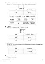
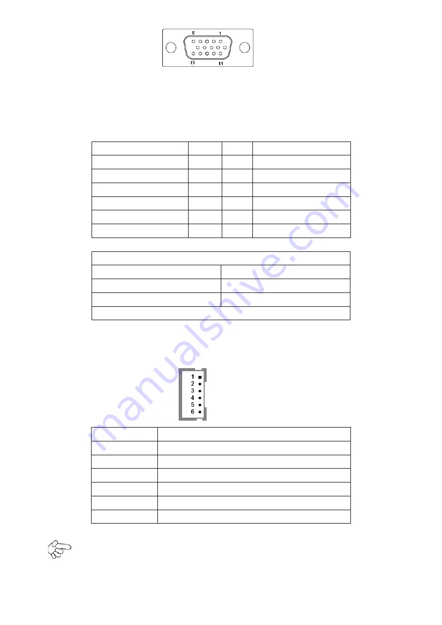
12. VGA_PH
(option)
:
(CRT 2.0mm Pitch 2X6 Pin Header), Video Graphic Array Port, Provide 2x5Pin cable to VGA Port,
they can not work at the same time for VGA and VGA_PH
.
Signal Name
Pin#
Pin#
Signal Name
CRT_RED
1
2
Ground
CRT_GREEN
3
4
Ground
CRT_BLUE
5
6
VGA_EN
CRT_H_SYNC
7
8
CRT_DDCDATA
CRT_V_SYNC
9
10
CRT_DDCCLK
Ground
11
12
Ground
VGA hot plug setting for Windows XP
:
VGA1
(
Pin Header
)
Function
Pin4-Pin6
(
Close
)
VGA Simulation Disabled
Pin4-Pin6
(
Open
)
VGA Simulation Enabled
use the 2.0mm jumper cap to close pin 4 and pin6
13. INVT1:
(2.0mm Pitch 1x6 Pin wafer connector), Backlight control connector for LVDS1.
Pin#
Signal Name
1
+DC12V
2
+DC12V
3
Ground
4
Ground
5
BKLT_EN
6
BKLT_CTRL
Note:
Pin6 is backlight control signal, support DC or PWM mode, mode select at BIOS CMOS menu.
Содержание NV-266 C Series
Страница 7: ...NV 266XC User Manual 7 Figure 1 1 Dimensions of NV 2663C ...
Страница 8: ...NV 266XC User Manual 8 Figure 1 2 Dimensions of NV 2664C ...
Страница 9: ...NV 266XC User Manual 9 Figure 1 3 Dimensions of NV 2665C ...
Страница 12: ...NV 266XC User Manual 12 Figure 1 9 Rear view of NV 2665C ...
Страница 16: ...NV 266XC User Manual 16 2 2 Board Dimensions ...
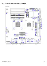
Страница 17: ...NV 266XC User Manual 17 2 3 Jumpers and Connectors Location Board Top ...
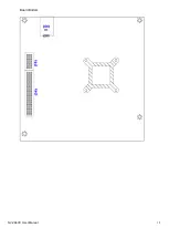
Страница 18: ...NV 266XC User Manual 18 Board Bottom ...
Страница 66: ...NV 266XC User Manual 66 Step 3 Click I agree Step 4 Click Continue Anyway ...
Страница 67: ...NV 266XC User Manual 67 Step 5 Click Continue Anyway Step 6 Click Yes to restart the computer ...
Страница 72: ...NV 266XC User Manual 72 Step 3 Click Yes ...


