NV-266XC User Manual
20
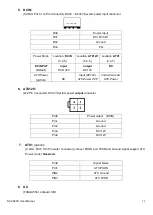
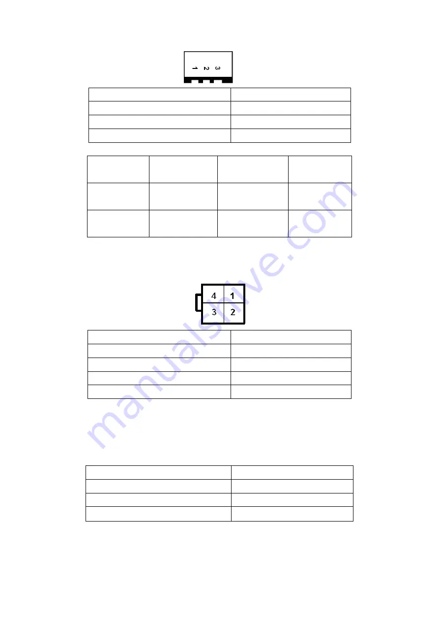
5. DCIN:
(5.08mm Pitch 1x3 Pin Connector),DC9V ~ DC32V System power input connector
。
Pin#
Power Input
Pin1
DC+9V~32V
Pin2
Ground
Pin3
PG
Power Mode
Location :
DCIN
(5.4.5.)
Location:
ATX12V
(5.4.6.)
Location:
ATX1
(5.4.7.)
DC INPUT
(Default)
input
DC9~32V
output
DC 12V
NC
ATX Power
(option)
NC
Input (DC12V)
ATX Power 2*2P
PSON,GND,5VSB
ATX Power
6. ATX12V:
(2x2 Pin Connector),DC12V System power
output
connector.
Pin#
Power output (DCIN)
Pin1
Ground
Pin2
Ground
Pin3
DC+12V
Pin4
DC+12V
7. ATX1
(option)
:
(2.0mm Pitch 1X3 Pin wafer connector),connect PSON and 5VSB and Ground signal,support ATX
Power model.
Reserved
.
Pin#
Signal Name
Pin1
ATX PSON
PIN2
ATX Ground
PIN3
ATX 5VSB
8. U2:
(FCBGA559), onboard CPU .
Содержание NV-266 C Series
Страница 7: ...NV 266XC User Manual 7 Figure 1 1 Dimensions of NV 2663C ...
Страница 8: ...NV 266XC User Manual 8 Figure 1 2 Dimensions of NV 2664C ...
Страница 9: ...NV 266XC User Manual 9 Figure 1 3 Dimensions of NV 2665C ...
Страница 12: ...NV 266XC User Manual 12 Figure 1 9 Rear view of NV 2665C ...
Страница 16: ...NV 266XC User Manual 16 2 2 Board Dimensions ...
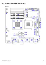
Страница 17: ...NV 266XC User Manual 17 2 3 Jumpers and Connectors Location Board Top ...
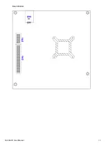
Страница 18: ...NV 266XC User Manual 18 Board Bottom ...
Страница 66: ...NV 266XC User Manual 66 Step 3 Click I agree Step 4 Click Continue Anyway ...
Страница 67: ...NV 266XC User Manual 67 Step 5 Click Continue Anyway Step 6 Click Yes to restart the computer ...
Страница 72: ...NV 266XC User Manual 72 Step 3 Click Yes ...


