D.8
Routing
E
UTILITY PAGES
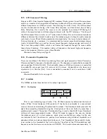
non-VX mode, this delay will depend on the lowest high-pass frequency used in the crossover
filters in a given Drive Module. In VX mode, the delay is related to the Split frequency. This
delay will be applied to all of the outputs in a given Drive Module to keep them in phase.
Also see Latency Delays on page 25.
D.7.2
Tmax Thermal Limiter
The Thermal Limiter is intended to protect the driver against damage due to over-heating.
This protection is calibrated by APG and cannot be modified.
Also see Amplifier Gain on this
page.
D.7.3
Xmax Excursion Limiter
The Excursion Limiter protects the driver against excessive linear movement of the cone and
voice-coil which could otherwise cause mechanical damage. This protection is calibrated by
APG and cannot be modified.
Also see Amplifier Gain on the current page.
D.7.4
Amplifier Gain
Expressed in dB, this is the gain of the amplifier which the output of the DMS48 is feeding.
This value must be entered to allow the DMS48 to correctly calibrate the thermal and excursion
limiter for the amplifier in use.
D.8
Routing
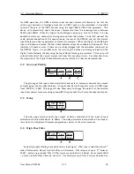
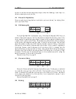
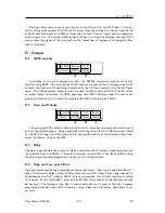
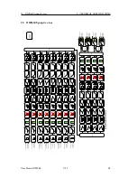
Outputs can be driven from any DSP input. This routing is the fundamental means by which
Drive Modules are created.
Also see Drive Modules on page 9.
E
Utility Pages
E.1
Screen Contrast
U
Screen
50%
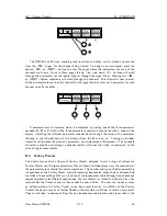
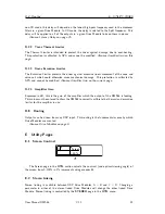
The Screen page in the
UTIL
section adjusts the contrast (and optimal viewing angle) of
the screen from 0-100% in 1% increments using encoder
A
.
E.2
Stereo Linking
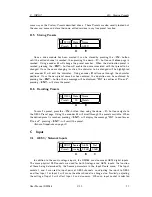
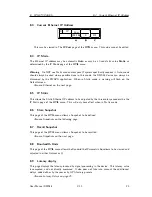
Stereo linking is available between DSP Drive Modules A + B and C + D. Changing a
parameter in either of the stereo linked Drive Modules will change the other linked Drive
Module. Stereo linking is controlled by the
STEREO
page in the
UTIL
menu.
User Manual DMS48
V1.1
22
Содержание DMS48
Страница 1: ...User Manual Digital Processor DMS48...
Страница 2: ......
Страница 29: ......
Страница 30: ......
Страница 31: ......

