A
MENU BUTTONS
The User Guide
This user manual gives a progressively more detailed description of the functions of the APG
DMS48 processor. A single page quick reference guide is provided for those users who are
experienced with this type of equipment and just need to know how to drive the front panel. A
detailed explanation of the front and rear panel controls and indicators is contained in the next
section. The final section describes each individual function or feature with annotated images
explaining its use. Where appropriate, the graphical display is shown to further elaborate on
the units operation. To complete the manual a reference section is included, describing the
technical performance of the device complete with graphs of filter responses and details of the
Drive Module presets and their configuration.
A
Menu Buttons
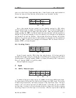
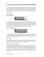
There are three buttons to determine which section of the device to view or edit. The
<
OUT
>
button displays pages of parameters associated with a particular output channel. The
<
IN
>
button displays pages of parameters associated with a particular input socket or input DSP
channel. Pressing
<
IN
>
or
<
OUT
>
buttons repeatedly will scroll through the inputs/outputs
of the processor. After the last channel, navigation returns to the default screen. The
<
UTIL
>
button displays pages of miscellaneous parameters not associated with any particular channel.
Whilst in Edit mode, one of these three buttons will be illuminated. They are mutually exclusive
pressing one of the buttons will deselect any others that are active.
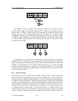
A.1
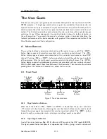
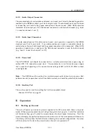
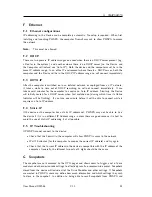
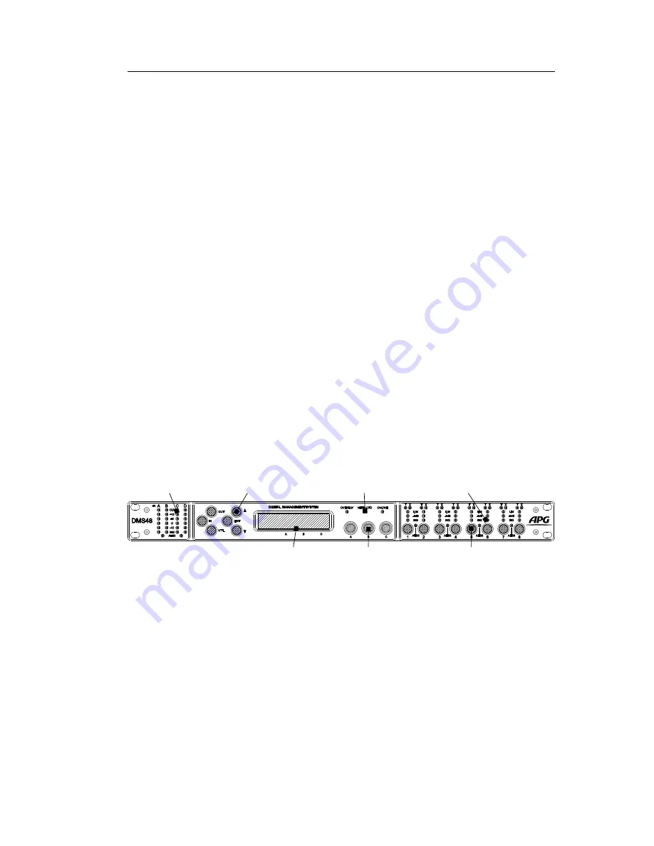
Front Panel
6-
Parameter
Encoders
4-
Graphical
Display
8- Output
Mute
Buttons
2/3- Input
Signal
Indicators
1- Page
Selection
Buttons
5-
Status
Indicators
7/9-
Limiters /AES3
Indicators
Figure 2: Front panel schema
A.1.1
Page Selection Buttons
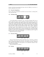
When one of the buttons
<
IN
>
,
<
OUT
>
or
<
UTIL
>
is illuminated, the up
<
N
>
and down
<
H
>
arrows will also illuminate, informing the user that these buttons may be used to scroll
through the various pages of parameters that may be viewed and edited. The
<
ENT
>
button
is used to confirm an operation such as storing or recalling a preset or snapshot
A.1.2
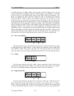
Input Signal Indicators
A set of five indicators show
Sig
,
-12
,
0
,
+6
and
+12
for each of the DSP inputs
A B C D
.
The signal present Indicators operate at approximately 40 dBu, giving a useful indication of
User Manual DMS48
V1.1
11
Содержание DMS48
Страница 1: ...User Manual Digital Processor DMS48...
Страница 2: ......
Страница 29: ......
Страница 30: ......
Страница 31: ......


