June 2013
14
80-0180-347 Rev. A
F
IG
. 14
F
IG
. 15
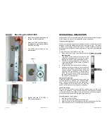
STEP 5 MORTISE CYLINDER INSTALLATION
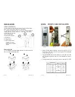
Using a Philips Head Screwdriver,
remove the eight (8) #10-32 x 5/8”
screws on the back of the eForce
®
and gently lift the back plate off the
housing.
C
AUTION
!
There are wires connect-
ing the housing and back plate
assembly. Handle with care.
Do not over-tighten!
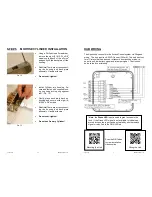
Install Cylinder into housing. Se-
cure and fasten with supplied lock-
ing ring using locking ring spanner
tool. (F
IG
. 15)
Gently place back plate back on
housing and secure with eight (8)
#10-32 x 5/8” screws.
C
AUTION
!
There are wires connect-
ing the housing and back plate
assembly. Handle with care.
Do not over-tighten!
Do not use Dummy Cylinder!
June 2013
7
80-0180-347 Rev. A
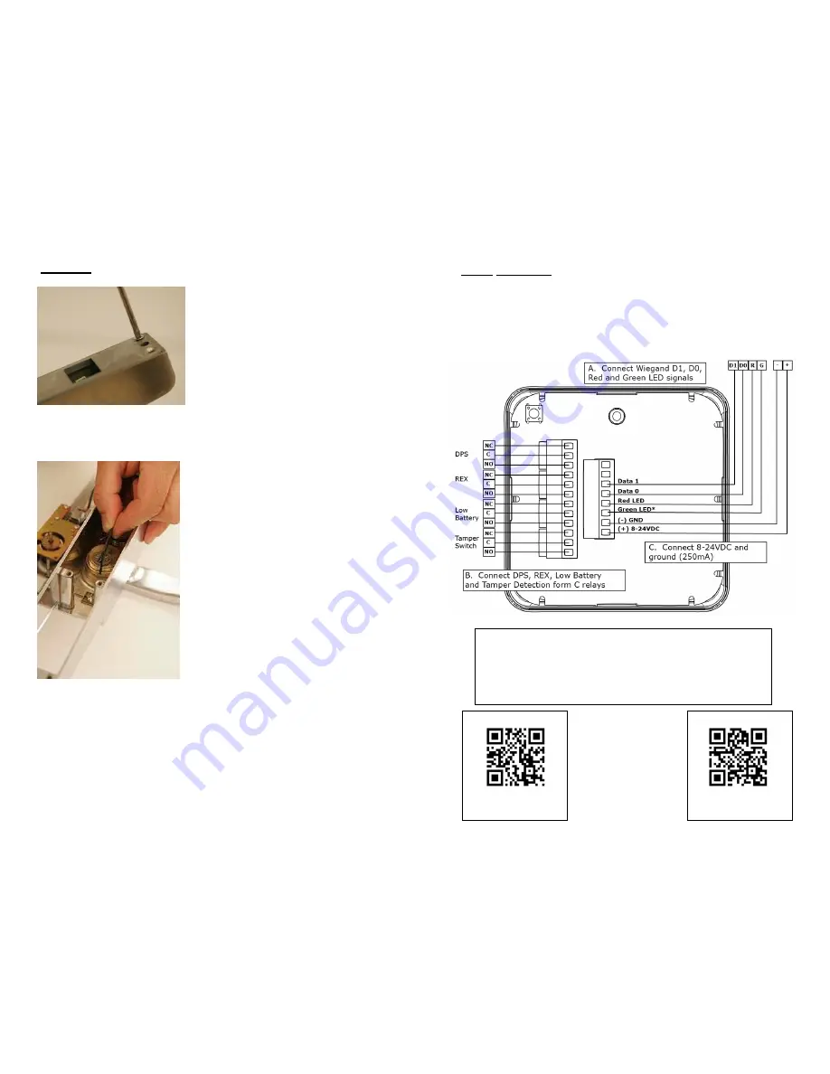
HUB WIRING
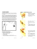
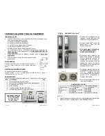
The Aperio hub connects to the Access Control system via Wiegand
wiring. The hub requires 8-24VDC power (250mA). The hub has four
form C relays that can be used to transmit door position status, re-
quest to exit, low battery signal and a tamper signal. The Hub con-
nects to the lock wirelessly.
Scan the QR Codes
to view installation
videos online.
*Note:
the
Green LED
input is used to grant access to the
lock. If the Green LED signal is not available to indicate ap-
proved access, the input can be activated by another unlock
signal or relay tied to the GRN LED pin
Wiring the Hub
Mounting the Hub

