June 2013
12
80-0180-347 Rev. A
RIM Exit Device Application: A100-3090H for 8700/8800
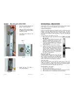
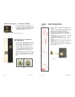
On the back side of the exit device, re-
move only the lower Phillips head screw,
depending on hand of door, to free up the
cylinder actuator for use. (F
IG
. 10)
MS 1850 Application: A100-3090H for
MS
®
Series Deadbolt
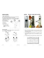
Two (2) brass hex head screws and the
set screw from the MS1850 will fasten
the cam plug to the MS1850. (F
IG
. 11)
For MS
®
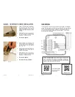
Deadbolt, insert Cam Plug (F
IG
.
12) into lock case with notch on the cam
plug aligned with lock case setscrew.
Tighten setscrew and secure with the
two (2) brass cam plug screws. Cam
Plug must be positioned below door sur-
face.
C
YLINDER
A
CTUATOR
SCREW
F
IG
. 11
F
IG
. 10
F
IG
. 12
June 2013
9
80-0180-347 Rev. A
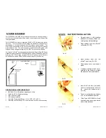
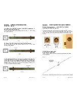
STEP 1 DOOR PREPARATION
F
IG
. 2
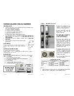
Select the stick-on template to match the appli-
cation.
For Yale, Corbin Russwin and SARGENT exit
devices, use template 80-0180-396-01.
Mark the backset and horizontal centerlines.
Apply
clear
template over the centerline marks
(F
IG
. 2).
Center-punch four (4) referenced mounting
holes and remove template.
Drill holes at center-punch locations using a ¼”
drill bit.
Install Rivnuts. Refer to instructions supplied in
Rivnut kit.
Install mounting bracket (Item 1) with two (2)
each of #10-32 x 5/8” (Item 2) Phillips pan
head screws. (F
IG
. 3)
F
IG
. 3

